C.9 MEMOBUS/Modbus Data Table
YASKAWA ELECTRIC SIEP C710616 27G YASKAWA AC Drive A1000 Technical Manual 559
MEMOBUS/Modbus
Communications
C
C.9 MEMOBUS/Modbus Data Table
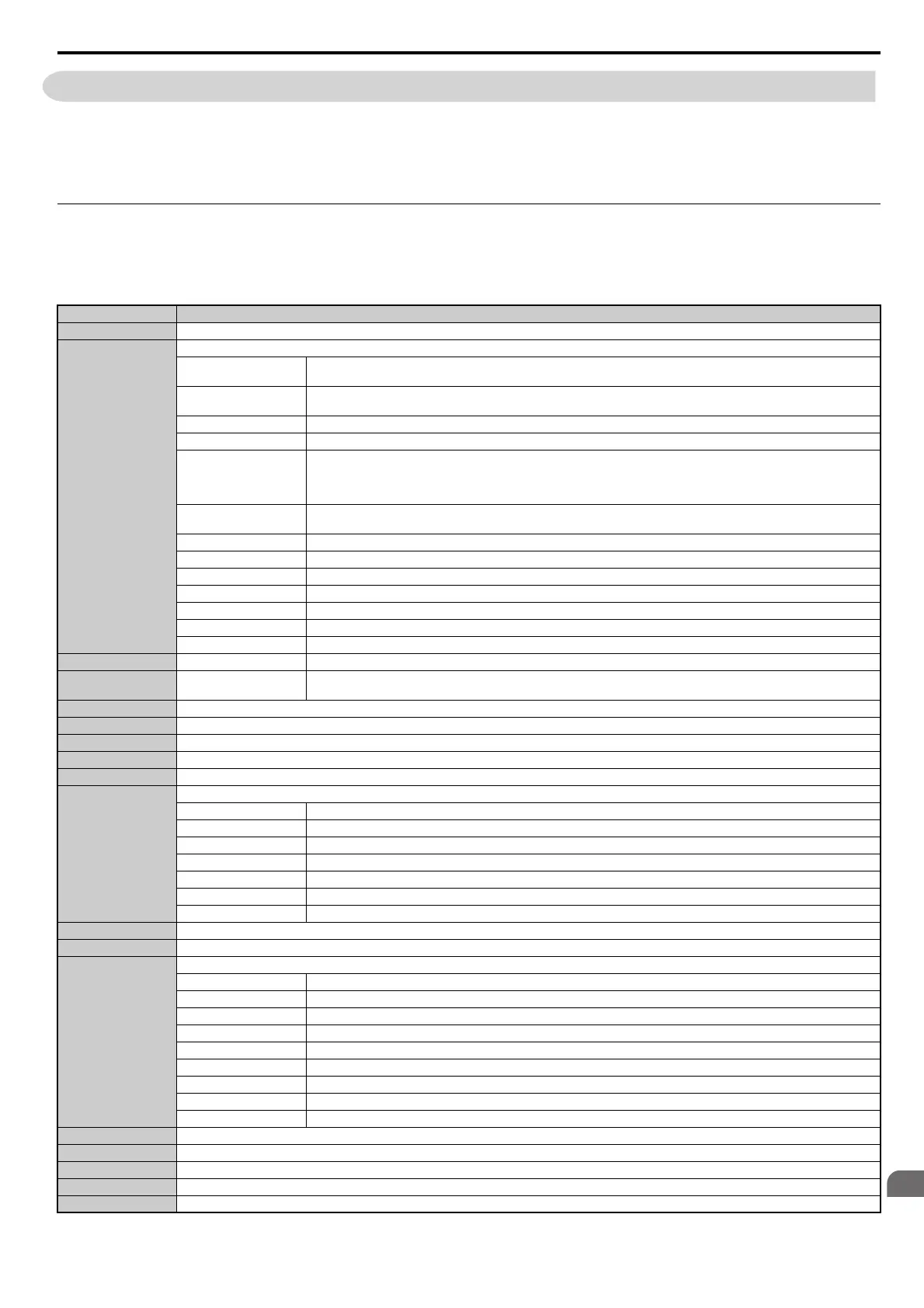
Table below lists all MEMOBUS/Modbus data. There are three types of data: command data, monitor data, and
broadcast data.
The MEMOBUS register hex addresses for parameters are listed in Parameter Table on page 453.
Command Data
It is possible to both read and write command data.
Note: Bits that are not used should be set to 0. Refrain from writing to reserved registers.
Register No. Contents
0000H Reserved
0001H
Operation Commands and Multi-function Inputs
bit 0
H5-12 = 0: Forward Run Command (0 = Stop, 1 = Forward Run)
H5-12 = 1: Run Command (0 = Stop, 1 = Run)
bit 1
H5-12 = 0: Reverse Run Command (0 = Stop, 1 = Reverse Run)
H5-12 = 1: Forward/Reverse (0 = Forward, 1 = Reverse)
bit 2 External Fault (EF0)
bit 3 Fault Reset
bit 4
Multi-Function Input 1
Function is ComRef when H1-01 = 40 (Forward/Stop).
Note: When the bit at ComCtrl is turned on, commands from MEMOBUS/Modbus communications take control of the operation.
However, when a communications option card is connected, that option card is given priority.
bit 5
Multi-Function Input 2
Function is ComCtrl when H1-02 = 41 (Reverse/Stop).
bit 6 Multi-Function Input 3
bit 7 Multi-Function Input 4
bit 8 Multi-Function Input 5
bit 9 Multi-Function Input 6
bit A Multi-Function Input 7
bit B Multi-Function Input 8
bit C to F Reserved
0002H Frequency Reference Units are determined by parameter o1-03.
0003H Output voltage gain
Unit: 0.1%
Range: 20 (2.0%) to 2000 (200.0%), Default when power on: 1000 (100.0%)
0004H Torque Reference/Torque Limit, 0.1% units, signed (Usable only if Torque Control is enabled)
0005H Torque Compensation, 0.1% units, signed (Usable only if Torque Control is enabled)
0006H PID Target, 0.01% units, signed
0007H Analog Output Terminal FM Setting (10 V / 4000 H)
0008H Analog Output Terminal AM Setting (10 V / 4000 H)
0009H
Settings for Multi-Function Digital Outputs
bit 0 Multi-Function Contact Output (terminal M1-M2)
bit 1 Multi-Function Contact Output 2 (terminal M3-M4)
bit 2 Multi-Function Contact Output 2 (terminal M5-M6)
bit 3 to 5 Reserved
bit 6 Enables the function in bit 7
bit 7 Fault Contact Output (terminal MA/MB-MC)
bit 8 to F Reserved
000AH Pulse Output Terminal MP Setting, 1 Hz units, Setting Range: 0 to 32000
000BH to 000EH Reserved
000FH
Control Selection Setting
bit 0 Reserved
bit 1 PID Setpoint Input
bit 2 Torque reference / torque limit input (enables the setting from MEMOBUS/Modbus)
bit 3 Torque compensation input (enables the setting from MEMOBUS/Modbus)
bit 4 to B Reserved
bit C Enable Terminal S5 Input for Broadcast Data
bit D Enable Terminal S6 Input for Broadcast Data
bit E Enable Terminal S7 Input for Broadcast Data
bit F Enable Terminal S8 Input for Broadcast Data
0010H to 001AH Reserved
001BH Analog Monitor Option AO-A3 Analog Output 1 (10 V/4000 H)
001CH Analog Monitor Option AO-A3 Analog Output 2 (10 V/4000 H)
001DH Digital Output Option DO-A3 Output (Binary)
001EH to 001FH Reserved