336 YASKAWA ELECTRIC SIEP C710616 27G YASKAWA AC Drive A1000 Technical Manual
6.4 Fault Detection
6.4 Fault Detection
Fault Displays, Causes, and Possible Solutions
Faults are detected for drive protection that cause the drive to stop while toggling the form-C output associated with
terminals MA-MB-MC.
Remove the cause of the fault and manually clear the fault bef
ore attempting to run the drive again.
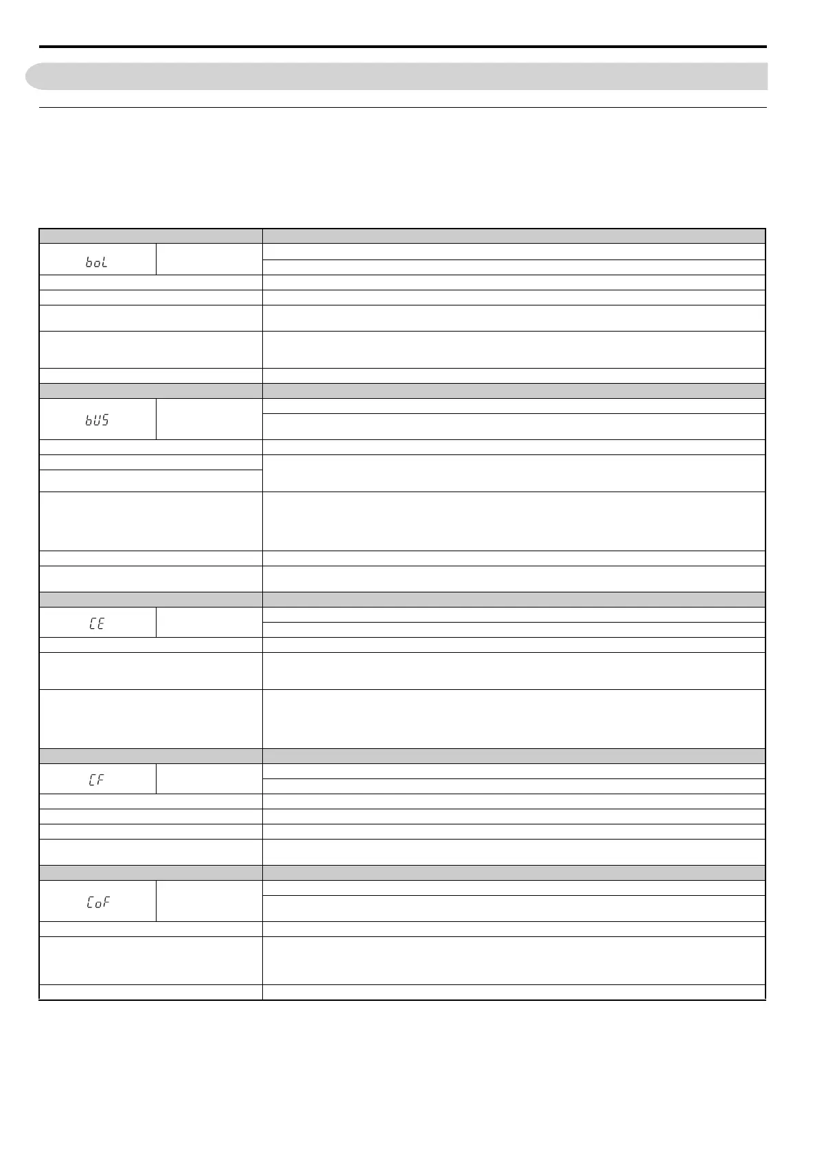
Table 6.15 Detailed Fault Displays, Causes, and Possible Solutions
Digital Operator Display Fault Name
boL
Braking Transistor Overload Fault
The
braking transistor has reached its overload level.
Cause Possible Solution
The wrong braking resistor is installed.
Select the optimal braking resistor.
Use a regen converter, regen unit, braking unit, or other
device to connect the +1 or +3 terminal to the - terminal.
Set L8-55 to 0 to disable Internal Braking Transistor Protection.
The braking transistor use rate is high (i.e., the regen
converter is large or the repetition frequency is high).
• Change to a CDBR type braking unit.
• Change to a regen converter.
• Increase the deceleration time.
The braking transistor inside the drive is faulty. Replace the drive.
Digital Operator Display Fault Name
bUS
Option Communication Error
• After establishing initial communi
cation, the connection was lost.
• Only detected when the run command frequency referen
ce is assigned to an option card.
Cause Possible Solution
No signal received from the PLC. • Check for faulty wiring.
• Correct the wiring.
• Check for disconnected cables and s
hort circuits. Repair as needed.
Faulty communications wiring or a short circuit exists.
A
communications data error occurred due to noise.
• Check the various options available to minimize the effects of noise.
• Take steps to counteract noise in the control circuit
, main circuit, and ground wiring.
• Ensure that other equipment such as switches or relays d
o not cause noise. Use surge suppressors if necessary.
• Use only recommended cables or other shielded
line. Ground the shield on the controller side or on the drive input power side.
• Separate all communication wiring from drive power lines. I
nstall an EMC noise filter to the drive power supply input.
The option card is damaged. • Replace the option card if there are no problems wi
th the wiring and the error continues to occur.
The option card is not properly connected to the drive.
• The connector pins on the option card are not properly
lined up with the connector pins on the drive.
• Reinstall the option card.
Digital Operator Display Fault Name
CE
MEMOBUS/Modbus Communication Error
C
ontrol data was not received for the CE detection time set to H5-09.
Cause Possible Solution
Faulty communications wiring or a short circuit exists.
• Check for faulty wiring.
• Correct the wiring.
• Check for disconnected cables and s
hort circuits. Repair as needed.
Communication data error o
ccurred due to noise.
• Check the various options available to minimize the effects of noise.
• Take steps to counteract noise in the control circuit
, main circuit, and ground wiring.
• Use only recommended cables or other shielded
line. Ground the shield on the controller side or on the drive input power side.
• Ensure that other equipment such as switches or relays d
o not cause noise and use surge suppressors if required.
• Separate all communication wiring from drive power lines. Install an EMC noise filter to the drive power supply input.
Digital Operator Display Fault Name
CF
Control Fault
A
torque limit was reached continuously for three seconds or longer while ramping to stop in Open Loop Vector Control.
Cause Possible Solution
Motor parameters are not set prope
rly. Check the motor parameter settings and repeat Auto-Tuning.
Torque limit is too low. Set the torque limit to the most appropriate setting (L7-01 through L7-04).
Load inertia is too big.
• Adjust the deceleration time (C1-02, C1-04, C1-06, C1-08).
• Set the frequency to the minimum value and interrupt the Run command when the drive finishes decelerating.
Digital Operator Display Fault Name
CoF
Current Offset Fault
Th
e current sensor is damaged or there was residual induction current in the motor (e.g., during sudden deceleration or when
coasting) when the drive attempted to start the motor.
Cause Possible Solution
Due to residual induction current in the motor when the
dr
ive attempted to start the motor, the drive attempted to
adjust the current offset value beyond the allowable
range.
• Create a motor restart sequence that allows enough ti
me for the residual induction voltage to dissipate.
• Enable Speed Search at start (b3-01 = 1). Use the multi-funct
ion terminals to execute External Speed Search 1 and 2 (H1- =
61 or 62).
Note:
When using a PM motor, both External Speed Search 1 and 2 perform the same operation.
Hardware is damaged. Replace the drive. Replace the drive.