8.4 Option Card Installation
YASKAWA ELECTRIC SIEP C710616 27G YASKAWA AC Drive A1000 Technical Manual 417
Peripheral Devices &
Options
8
8.4 Option Card Installation
This section provides instructions on installing the option cards listed in Table 8.1.
Prior to Installing the Option
Prior to installing the option, wire the drive, make the necessary connections to the drive terminals, and verify that the
drive functions normally. Refer to the Table 8.2 for information on wiring and connec
ting the drive.
Table 8.2 below lists the number of option cards that can be connec
ted to the drive and the drive connectors for
connecting those option cards.
Table 8.2 Option Card Installation
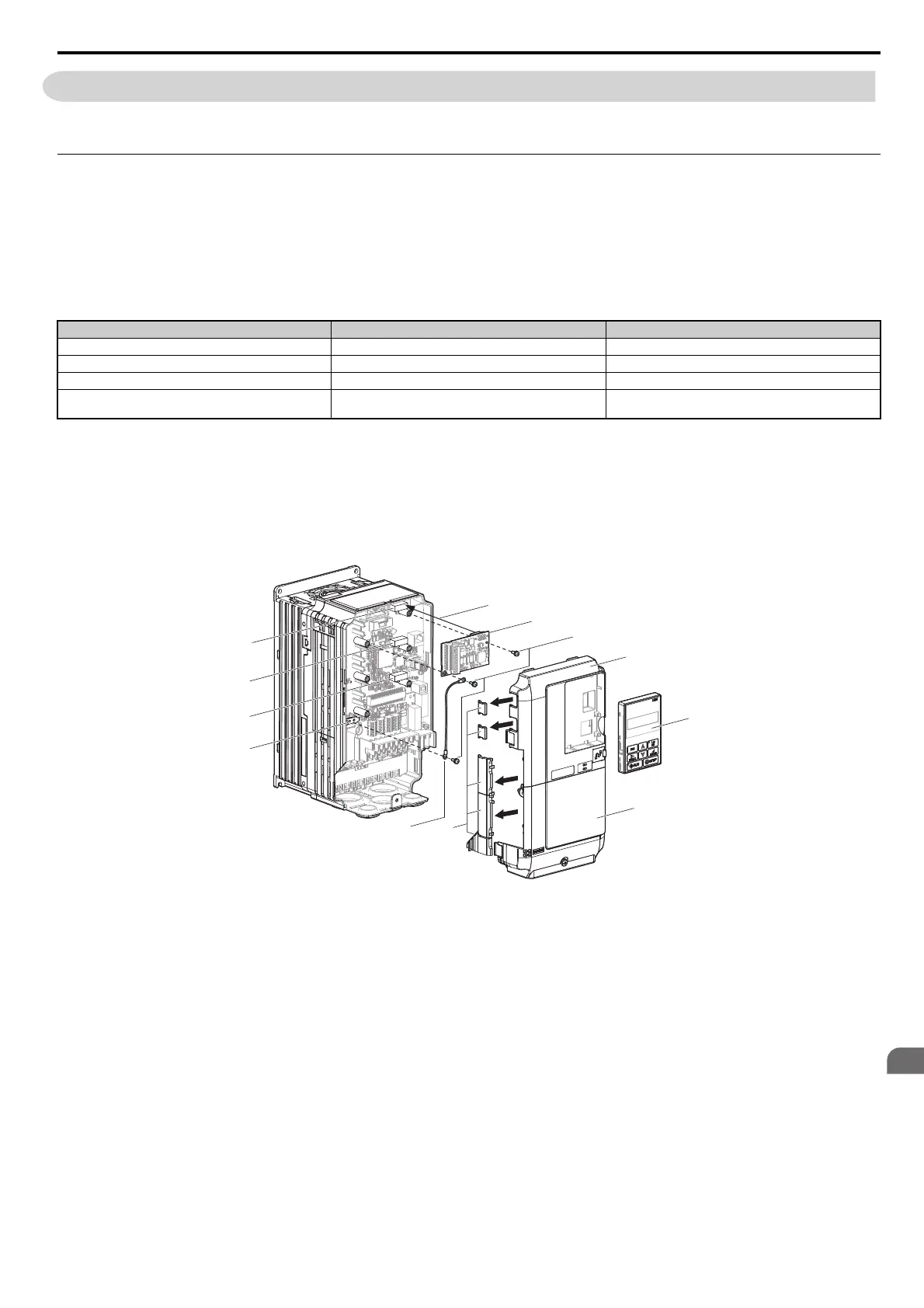
Figure 8.2 shows an exploded view of the drive with the option and related components for reference.
Figure 8.2
Figure 8.2 Drive Components with Option
Option Card
<1> If only one PG option card is connected to the drive, use the CN5-C connector. If two PG option cards are connected, use both CN5-B and
CN5-C.
<2> These option cards are not available for the application with Motor 2 Selection.
<3> These option cards are not available with models CIMR-A4A0930 and 4A1200.
<4> When AI-A3 and DI-A3 are to be used as monitors, the card can be connected to any of CN5-A, CN5-B or CN5-C. The input status of AI-A3
can then be viewed using U1-21, U1-22, and U1-23, and the input status of DI-A3 can then be viewed using U1-17.
Connector Number of Cards Possible
PG-B3, PG-X3
CN5-C (CN5-B) <1> 2 <1>
PG-RT3 <2> <3>, PG-F3 <2> <3> CN5-C 1
DO-A3, AO-A3 CN5-A, B, C 1
SI-C3, SI-EM3, SI-EN3, SI-ET3, SI-
N3, SI-P3, SI-S3, SI-T3,
SI-W3, AI-A3
<4>, DI-A3 <4>
CN5-A 1
A – Insertion point for CN5 G – Removable tabs for wire routing
B – Option card H – Ground wire
C – Included screws I – Drive grounding terminal (FE)
D – Front cover J – Connector CN5-A
E – Digital operator K – Connector CN5-B
F – Terminal cover L – Connector CN5-C
G
A
B
C
H
D
E
F
I
J
K
L