5.10 o: Operator Related Settings
YASKAWA ELECTRIC SIEP C710616 27G YASKAWA AC Drive A1000 Technical Manual 319
o4-03: Cooling Fan Operation Time Setting
Sets the value for how long the cooling fan has been operating. This value can be viewed in monitor U4-03. Parameter
o4-03 also sets the base value used for the cooling fan maintenance, which is displayed in U4-04. Be sure to reset this
parameter back to 0 if the cooling fan is replaced.
Note: 1. The value in o4-03 increases after every 10 hours of use. A setting of 30 will set the cooling fan operation time counter to 300 h.
“300” will be displayed in monitor U4-03.
2. The
cooling fan may require maintenance at an earlier date in harsher environments.
o4-05: Capacitor Maintenance Setting
Sets value of the maintenance monitor for the DC bus capacitors displayed in U4-05 as a percentage of the total expected
performance life. This value should be reset to 0 when the DC bus capacitors have been replaced.
Note: The actual maintenance time will depend on the environment where the drive is used.
o4-07: DC Bus Pre-Charge Relay Maintenance Setting
Sets the value of the softcharge bypass relay maintenance time displayed in U4-06 as a percentage of the total expected
performance life. This value should be reset to 0 when the bypass relay has been replaced.
Note: The actual maintenance time will depend on the environment where the drive is used.
o4-09: IGBT Maintenance Setting
Sets the value of the IGBT maintenance time displayed in U4-07 as a percentage of the total expected performance life.
This value should be reset to 0 when the IGBTs have been replaced.
Note: The actual maintenance time will depend on the environment where the drive is used.
o4-11: U2, U3 Initialization
Resets the fault trace and fault history monitors (U2- and U3-). Initializing the drive using A1-03 does not reset
these monitors.
Setting 0: No action
The drive keeps the record already saved concerning fault trace and fault history.
Setting 1: Reset fault data
Resets the data for the U2- and U3- monitors. Setting o4-11 to 1 and pressing the ENTER key erases fault data
and returns the display to 0.
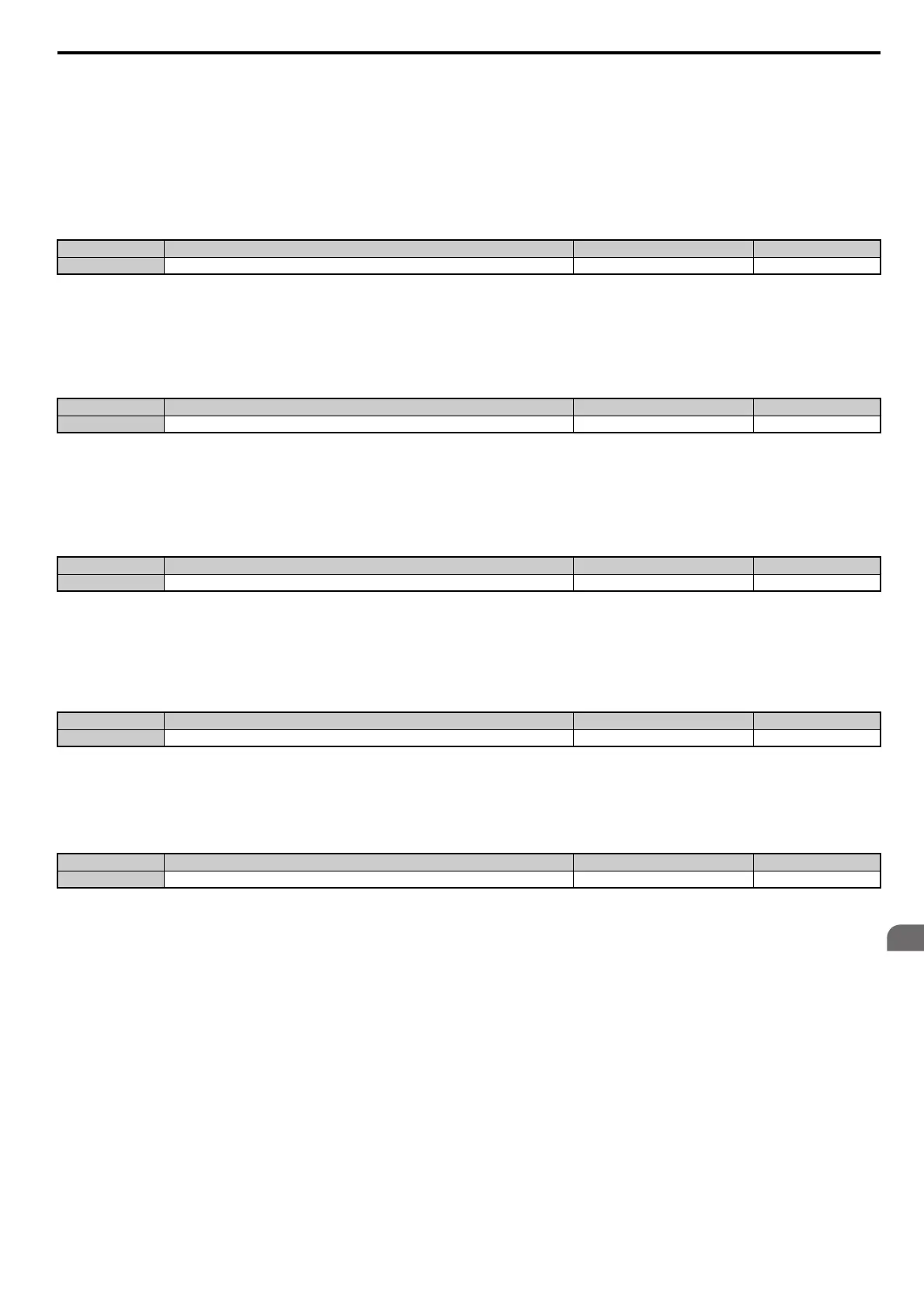
No. Name Setting Range Default
o4-03 Cooling Fan Operation Time Setting 0 to 9999 0
No. Name Setting Range Default
o4-05 Capacitor Maintenance Setting 0 to 150% 0%
No. Name Setting Range Default
o4-07 DC Bus Pre-charge Relay Maintenance Setting 0 to 150% 0%
No. Name Setting Range Default
o4-09 IGBT Maintenance Setting 0 to 150% 0%
No. Name Setting Range Default
o4-11 U2, U3 Initialization 0 or 1 0

 Loading...


