B.3 Parameter Table
504 YASKAWA ELECTRIC SIEP C710616 27G YASKAWA AC Drive A1000 Technical Manual
n8-36
(563H)
High Frequency Injection Level
There is normally no need to change this parameter from the default value.
Sets the frequency in Hz for the superimposed signal used for superimposed harmonics.
Enabled when n8-57 = 1.
Note: This parameter is not available with models CIMR-A4A0930 and 4A1200.
Default: 500 Hz
Min: 200 Hz
Max: 1000 Hz
310
n8-37
(564H)
High Frequency Injection
Amplitude
There is normally no need to change this parameter from the default value.
Sets the amplitude for High Frequency Injection as a percentage of the voltage when the voltage
class base is 100% (200 V Class is 200 V and, 400 V Class is 400 V). Adjust this value when
there is too much or too little current as a result of the settings assigned to motor parameters.
Enabled when n8-57 = 1.
Note: This parameter is not available with models CIMR-A4A0930 and 4A1200.
Default: 20.0%
Min: 0.0%
Max: 50.0%
310
n8-39
(566H)
Low Pass Filter Cutoff Frequency
for High Frequency Injection
There is normally no need to change this parameter from the default value.
Sets the cutoff frequency of a low pass filter for high frequency injection. Enabled when n8-57
= 1.
Note: This parameter is not available with models CIMR-A4A0930 and 4A1200.
Default: 50 Hz
Min: 0 Hz
Max: 1000 Hz
310
n8-45
(538H)
Speed Feedback Detection Control
Gain (for PM Motors)
Increase this setting if hunting occurs. Decrease to lower the response.
Default: 0.80
Min: 0.00
Max: 10.00
310
n8-47
(53AH)
Pull-In Current Compensation
Time Constant (for PM Motors)
Sets the time constant to make the pull-in current reference and actual current value agree.
Decrease the value if the motor begins to oscillate, and increase the value if it takes too long for
the current reference to equal the output current.
Default: 5.0 s
Min: 0.0 s
Max: 100.0 s
310
n8-48
(53BH)
Pull-In Current (for PM Motors)
Defines the d-axis current reference during no-load operation at a constant speed. Set as a
percentage of the motor rated current. Increase this setting if hunting occurs while running at
constant speed.
Default: 30%
Min: 20%
Max: 200%
311
n8-49
(53CH)
d-Axis Current for High Efficiency
Control (for PM Motors)
Sets the d-axis current reference when running a high load at constant speed. Set as a percentage
of the motor rated current.
Default
:
<14>
Min: -200.0%
Max: 0.0%
311
n8-51
(53EH)
Acceleration/Deceleration Pull-In
Current (for PM Motors)
Sets the d-axis current reference during acceleration/deceleration as a percentage of the motor
rated current. Set to a high value when more starting torque is needed.
Default: 50%
Min: 0%
Max: 200%
311
n8-54
(56DH)
Voltage Error Compensation Time
Constant
Adjusts the value when hunting occurs at low speed. If hunting occurs with sudden load
changes, increase n8-54 in increments of 0.1. Increase this setting if vibration occurs at start.
Default: 1.00 s
Min: 0.00 s
Max: 10.00 s
311
n8-55
(56EH)
Load Inertia
Sets the ratio between motor and machine inertia.
0: Below 1:10
1: Between 1:10 and 1:30
2: Between 1:30 and 1:50
3: Beyond 1:50
Default: 0
Min: 0
Max: 3
311
n8-57
(574H)
High Frequency Injection
0: Disabled. Disable when using an SPM motor.
1: Enabled. Use this setting to enhance the speed control range when using an IPM motor.
Default: 0
Min: 0
Max: 1
312
n8-62
(57DH)
Output Voltage Limit (for PM
Motors)
Prevents output voltage saturation. Should be set just below the voltage provided by the input
power supply.
Default: 200.0 V
<18>
Min: 0.0 V
Max: 230.0 V
<18>
312
n8-65
(65CH)
Speed Feedback Detection Control
Gain during ov Suppression
Sets the gain used for internal speed feedback detection during ov suppression
Default: 1.50
Min: 0.00
Max: 10.00
312
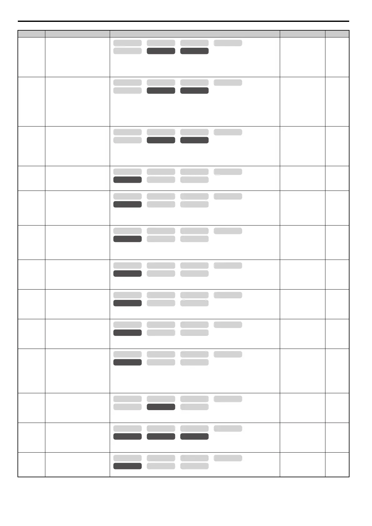
No. (Addr.) Name Description Setting Page
OLV/PM AOLV/PM
CLV
V/f w/PG
CLV/PM
V/f OLV
OLV/PM AOLV/PM
CLV
V/f w/PG
CLV/PM
V/f OLV
OLV/PM AOLV/PM
CLV
V/f w/PG
CLV/PM
V/f OLV
OLV/PM AOLV/PM
CLV
V/f w/PG
CLV/PM
V/f OLV
OLV/PM AOLV/PM
CLV
V/f w/PG
CLV/PM
V/f OLV
OLV/PM AOLV/PM
CLV
V/f w/PG
CLV/PM
V/f OLV
OLV/PM AOLV/PM
CLV
V/f w/PG
CLV/PM
V/f OLV
OLV/PM AOLV/PM
CLV
V/f w/PG
CLV/PM
V/f OLV
OLV/PM AOLV/PM
CLV
V/f w/PG
CLV/PM
V/f OLV
OLV/PM AOLV/PM
CLV
V/f w/PG
CLV/PM
V/f OLV
OLV/PM AOLV/PM
CLV
V/f w/PG
CLV/PM
V/f OLV
OLV/PM AOLV/PM
CLV
V/f w/PG
CLV/PM
V/f OLV
OLV/PM AOLV/PM
CLV
V/f w/PG
CLV/PM
V/f OLV

 Loading...


