5.7 H: Terminal Functions
250 YASKAWA ELECTRIC SIEP C710616 27G YASKAWA AC Drive A1000 Technical Manual
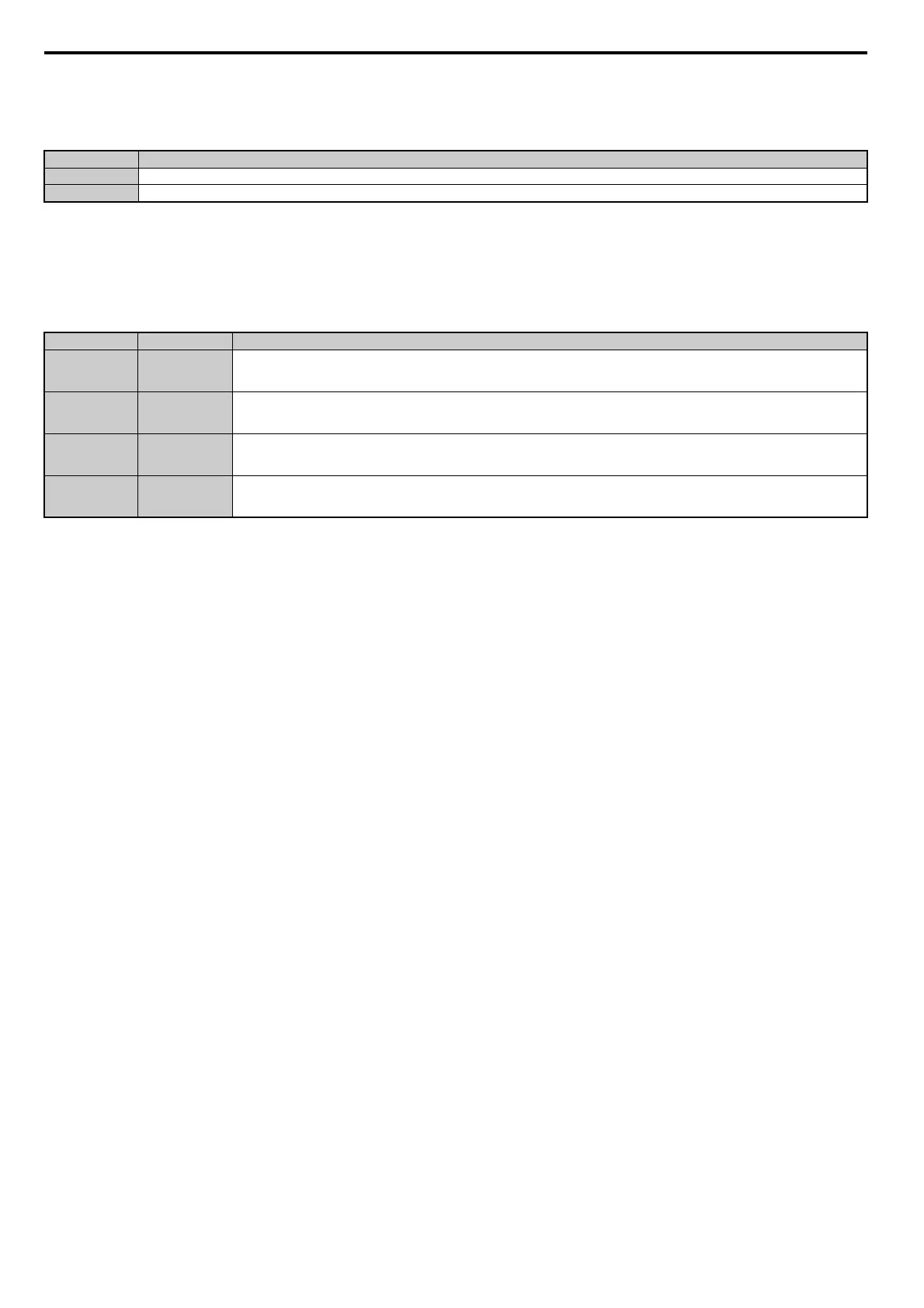
Setting A: Run command source
A digital output programmed for this function shows the Run command source that is currently selected.
Setting B, 17, 18, 19: Torque detection 1 (N.O., N.C.), Torque detection 2 (N.O., N.C.)
These digital output functions can be used to signal an overtorque or undertorque situation to an external device.
Set up the torque detection levels and select the output f
unction from the table below. Refer to L6: Torque Detection on
page 291 for details.
Setting C: Frequency reference loss
An output set for this function will be closed if frequency reference loss is detected. Refer to L4-05: Frequency
Reference Loss Detection Selection on page 289 for details.
Setting D: Braking resistor fault
An output programmed for this function will close when the dynamic braking resistor (DB) overheats or the braking
transistor is in a fault condition.
Setting E: Fault
The digital output will close whenever the drive experiences a fault (this excludes faults CPF00 and CPF01).
Setting F: Through mode
Select this setting when using the terminal in a pass-through mode. When set to F, an output does not trigger any function
in the drive. Setting F, however, still allows the output status to be read by a PLC via a communication option or
MEMOBUS/Modbus communications.
Setting 10: Minor fault
Output closes when a minor fault condition is present.
Setting 11: Fault reset command active
Output closes whenever there is an attempt to reset a fault situation from the control circuit terminals, via serial
communications, or using a communications option card.
Setting 12: Timer output
This setting configures a digital output terminal as output for the timer function. Refer to b4: Delay Timers on page 166
for details.
Status Description
Open Run command is provided from External reference 1 (b1-02) or 2 (b1-16).
Closed Run command is being sourced from the digital operator.
Setting Status Description
B Closed
Torque detection 1 (N.O.):
Output current/torque exceeds (overtorque detection) or is below (undertorque detection) the torque value set in parameter L6-02 for longer than
the time specified in parameter L6-03.
17 Open
Torque detection 1 (N.C.):
Output current/torque exceeds (overtorque detection) or is below (undertorque detection) the torque value set in parameter L6-02 for longer than
the time specified in parameter L6-03.
18 Closed
Torque detection 2 (N.O.):
Output current/torque exceeds (overtorque detection) or is below (undertorque detection) the torque value set in parameter L6-05 for longer than
the time specified in parameter L6-06.
19 Open
Torque detection 2 (N.C.):
Output current/torque exceeds (overtorque detection) or is below (undertorque detection) the torque value set in parameter L6-05 for longer than
the time specified in parameter L6-06.

 Loading...


