B.3 Parameter Table
470 YASKAWA ELECTRIC SIEP C710616 27G YASKAWA AC Drive A1000 Technical Manual
E2: Motor 1 Parameters
E1-04
(303H)
Maximum Output Frequency
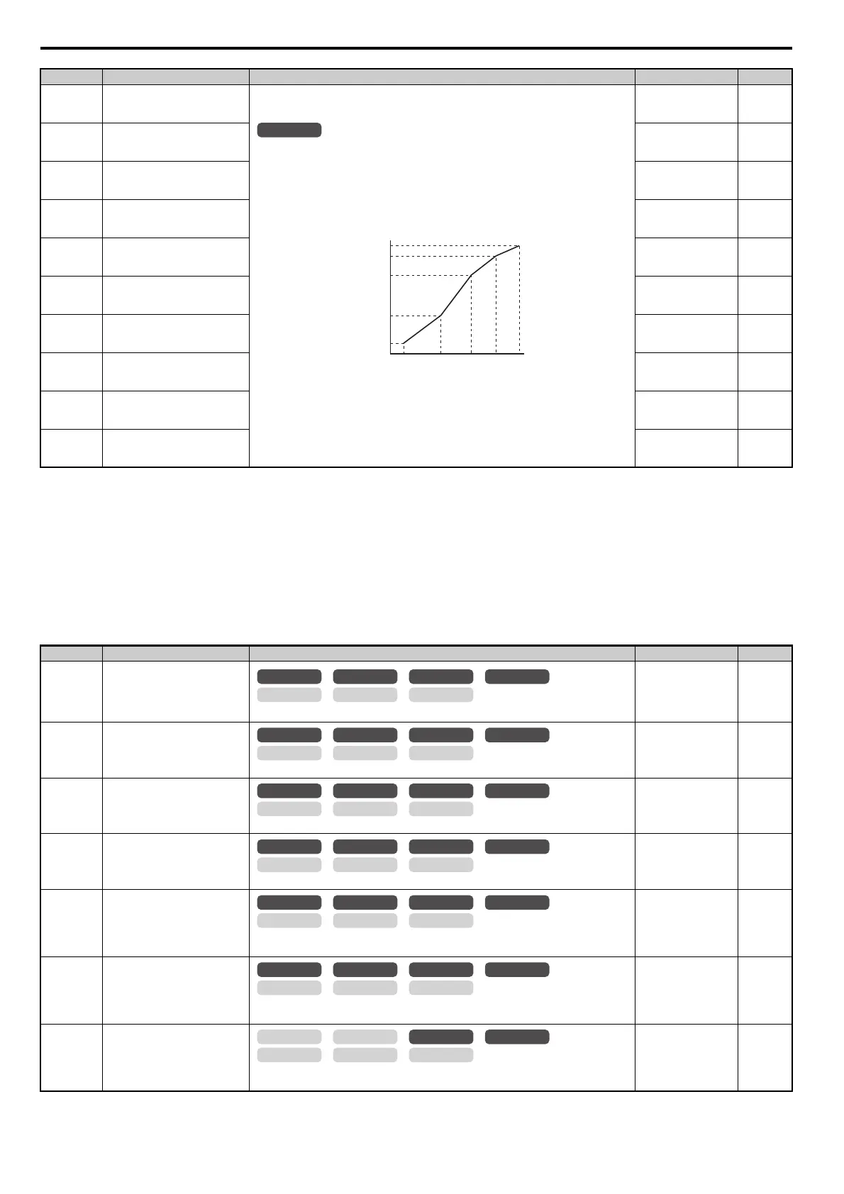
E1-04, E1-06 to E1-13 can only be changed when E1-03 is set to F.
To set linear V/f characteristics, set the same values for E1-07 and E1-09. In this case, the
setting for E1-08 will be disregarded. Ensure that the four frequencies are set according to these
rules or an oPE10 fault will occur:
E1-09 E1-07 < E1-06 E1-11 E1-04
Note that if E1-11 = 0, then both E1-11 and E1-12 are disabled, and the above conditions do not
apply.
Note: Some parameters may not be available depending on the control mode.
• E1-07, E1-08 and E1-10 are available only in the following control modes: V/f Control, V/f
with PG, Open Loop Vector.
• E1-11, E1-12 and E1-13 are available only in the following control modes: V/f Control, V/f
with PG, Open Loop Vector, Closed Loop Vector.
Default:
<4> <14>
Min: 40.0 Hz
Max: 400.0 Hz
<29>
216
E1-05
(304H)
Maximum Voltage
Default:
<4> <14> <18>
Min: 0.0 V
Max: 255.0 V
<18>
216
E1-06
(305H)
Base Frequency
Default:
<4> <14>
Min: 0.0
Max: E1-04
<29>
216
E1-07
(306H)
Middle Output Frequency
Default:
<4>
Min: 0.0
Max: E1-04
216
E1-08
(307H)
Middle Output Frequency Voltage
Default:
<4> <18>
Min: 0.0 V
Max: 255.0 V
<18>
216
E1-09
(308H)
Minimum Output Frequency
Default:
<4> <14>
Min: 0.0
Max: E1-04
<29>
216
E1-10
(309H)
Minimum Output Frequency
Voltage
Default:
<4> <18>
Min: 0.0 V
Max: 255.0 V
<18>
216
E1-11
(30AH)
<21>
Middle Output Frequency 2
Default: 0.0 Hz
Min: 0.0 Hz
Max: E1-04
216
E1-12
(30BH)
<21>
Middle Output Frequency Voltage
2
Default: 0.0 V
Min: 0.0 V
Max: 255.0 V
<18>
216
E1-13
(30CH)
<27>
Base Voltage
Default: 0.0 V
<18>
Min: 0.0 V
Max: 255.0 V
<18>
216
<3> Parameter setting value is not reset to the default value when the drive is initialized.
<4> Default setting is dependent on the control mode (A1-02), the drive model (o2-04), and the Drive Duty (C6-01).
<14> Default setting value is dependent on the motor code set to E5-01.
<18> Values shown here are for 200 V class drives. Double the value when using a 400 V class drive.
<21> Parameter ignored when E1-11 (Motor 1 Mid Output Frequency 2) and E1-12 (Motor 1 Mid Output Frequency Voltage 2) are set to 0.0.
<27> When E1-13 (Base Voltage) is set to 0.0, output voltage is controlled with E1-05 (Maximum Voltage) = E1-13. When Auto-Tuning is
performed, E1-05 and E1-13 are automatically set to the same value.
<29> The setting range varies according to the motor code entered to E5-01 when using OLV/PM. The setting range is 0.0 to 400.0 Hz when E5-01
is set to FFFF.
No.(Addr.) Name Description Setting Page
E2-01
(30EH)
Motor Rated Current
Sets the motor nameplate full load current in Amps. Automatically set during Auto-Tuning.
Default:
<9>
Min: 10% of drive rated
current
Max: 200% of drive
rated current
<19>
216
E2-02
(30FH)
Motor Rated Slip
Sets the motor rated slip. Automatically set during Auto-Tuning.
Default:
<9>
Min: 0.00 Hz
Max: 20.00 Hz
217
E2-03
(310H)
Motor No-Load Current
Sets the no-load current for the motor. Automatically set during Auto-Tuning.
Default:
<9>
Min: 0 A
Max: E2-01
<19>
217
E2-04
(311H)
Number of Motor Poles
Sets the number of motor poles. Automatically set during Auto-Tuning.
Default: 4
Min: 2
Max: 48
217
E2-05
(312H)
Motor Line-to-Line Resistance
Sets the phase-to-phase motor resistance. Automatically set during Auto-Tuning.
Note: The units are expressed in m in models CIMR-A4A0930 and 4A1200.
Default:
<9>
Min: 0.000
Max: 65.000
217
E2-06
(313H)
Motor Leakage Inductance
Sets the voltage drop due to motor leakage inductance as a percentage of motor rated voltage.
Automatically set during Auto-Tuning.
Default:
<9>
Min: 0.0%
Max: 40.0%
217
E2-07
(314H)
Motor Iron-Core Saturation
Coefficient 1
Sets the motor iron saturation coefficient at 50% of magnetic flux. Automatically set during
Auto-Tuning.
Default: 0.50
Min: 0.00
Max: 0.50
218
No.(Addr.) Name Description Setting Page
All Modes
Output Voltage (V)
Frequency (Hz)
E1-05
E1-12
E1-13
E1-08
E1-10
E1-09 E1-07 E1-06 E1-11 E1-04
OLV/PM AOLV/PM
CLV
V/f w/PG
CLV/PM
V/f OLV
OLV/PM AOLV/PM
CLV
V/f w/PG
CLV/PM
V/f OLV
OLV/PM AOLV/PM
CLV
V/f w/PG
CLV/PM
V/f OLV
OLV/PM AOLV/PM
CLV
V/f w/PG
CLV/PM
V/f OLV
OLV/PM AOLV/PM
CLV
V/f w/PG
CLV/PM
V/f OLV
OLV/PM AOLV/PM
CLV
V/f w/PG
CLV/PM
V/f OLV
OLV/PM AOLV/PM
CLV
V/f w/PG
CLV/PM
V/f OLV