B.3 Parameter Table
YASKAWA ELECTRIC SIEP C710616 27G YASKAWA AC Drive A1000 Technical Manual 471
E3: V/f Pattern for Motor 2
These parameters are hidden when a PM motor control mode has been selected for motor 1 (A1-02 = 5, 6, 7).
E2-08
(315H)
Motor Iron-Core Saturation
Coefficient 2
Sets the motor iron saturation coefficient at 75% of magnetic flux. Automatically set during
Auto-Tuning.
Default: 0.75
Min: E2-07
Max: 0.75
218
E2-09
(316H)
Motor Mechanical Loss
Sets the motor mechanical loss as a percentage of motor rated power (kW).
Default: 0.0%
Min: 0.0%
Max: 10.0%
218
E2-10
(317H)
Motor Iron Loss for Torque
Compensation
Sets the motor iron loss.
Default:
<9>
Min: 0 W
Max: 65535 W
218
E2-11
(318H)
Motor Rated Power
Sets the motor rated power in kilowatts. Automatically set during Auto-Tuning.
Default:
<9>
Min: 0.00 kW
Max: 650.00 kW
218
<9> Default setting value is dependent on the drive model (o2-04) and the Drive Duty (C6-01).
<19> Display is in the following units.
CIMR-A2A0004 to 2A0040, CIMR-A4A0002 to 4A0023: 0.01 A units
CIMR-A2A0056 to 2A0312, CIMR-A4A0031 to 4A0675: 0.1 A units
CIMR-A4A0930 to 4A1200: 1 A units
No.(Addr.) Name Description Setting Page
E3-01
(319H)
<18> Values shown here are for 200 V class drives. Double the value when using a 400 V class drive.
<24> Parameter ignored when E3-11 (Motor 2 Mid Output Frequency 2) and E3-12 (Motor 2 Mid Output Frequency Voltage 2) are set to 0.
<25> Default setting depends on the control mode for motor 2 set in parameter E3-01. The value shown here is for V/f Control.
<27> When E1-13 (Base Voltage) is set to 0.0, output voltage is controlled with E1-05 (Maximum Voltage) = E1-13. When Auto-Tuning is
performed, E1-05 and E1-13 are automatically set to the same value.
<61> When E3-13, Motor 2 Base Voltage, is set to 0.0, output voltage is controlled with E3-05, Motor 2 Maximum Voltage, = E3-13. When
Auto-Tuning is performed, E3-05 and E3-13 are automatically set to the same value.
Motor 2 Control Mode Selection
0: V/f Control
1: V/f Control with PG
2: Open Loop Vector Control
3: Closed Loop Vector Control
Default: 0
Min: 0
Max: 3
219
E3-04
(31AH)
Motor 2 Maximum Output
Frequency
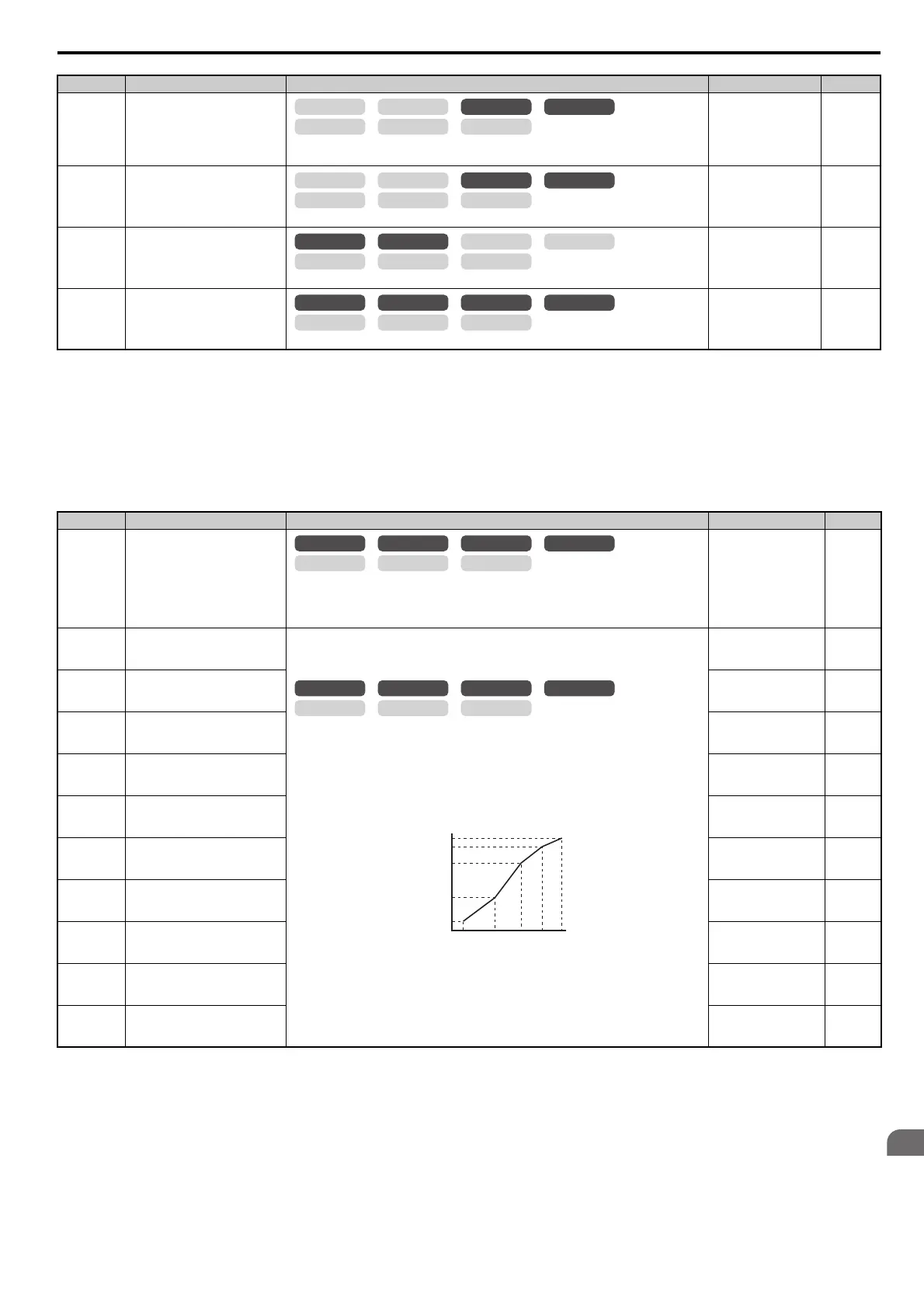
To set linear V/f characteristics, set the same values for E3-07 and E3-09. In this case, the
setting for E3-08 will be disregarded. Ensure that the five frequencies are set according to these
rules or an oPE10 fault will occur:
E3-09 E3-07 E3-06 E3-04
Note that if E3-11 = 0, then both E3-11 and E3-12 are disabled, and the above conditions do not
apply.
Note: E3-07 and E3-08 are only available in the following control modes: V/f, V/f w/PG and
OLV.
Default:
<25>
Min: 40.0 Hz
Max: 400.0 Hz
220
E3-05
(31BH)
Motor 2 Maximum Voltage
Default:
<18>
Min: 0.0 V
Max: 255.0 V
<18>
220
E3-06
(31CH)
Motor 2 Base Frequency
Default:
<25>
Min: 0.0 Hz
Max: E3-04
220
E3-07
(31DH)
Motor 2 Mid Output Frequency
Default:
<25>
Min: 0.0 Hz
Max: E3-04
220
E3-08
(31EH)
Motor 2 Mid Output Frequency
Vo l t a g e
Default:
<18> <25>
Min: 0.0 V
Max: 255.0 V
<18>
220
E3-09
(31FH)
Motor 2 Minimum Output
Frequency
Default:
<25>
Min: 0.0 Hz
Max: E3-04
220
E3-10
(320H)
Motor 2 Minimum Output
Frequency Voltage
Default:
<18> <25>
Min: 0.0 V
Max: 255.0 V
<18>
220
E3-11
(345H)
<24>
Motor 2 Mid Output Frequency 2
Default: 0.0 Hz
<24>
Min: 0.0 Hz
Max: E3-04
220
E3-12
(346H)
<24>
Motor 2 Mid Output Frequency
Voltage 2
Default: 0.0 V
Min: 0.0 V
Max: 255.0 V
<18>
220
E3-13
(347H)
<61>
Motor 2 Base Voltage
Default: 0.0 V
Min: 0.0 V
Max: 255.0 V
<18>
220
No.(Addr.) Name Description Setting Page
OLV/PM AOLV/PM
CLV
V/f w/PG
CLV/PM
V/f OLV
OLV/PM AOLV/PM
CLV
V/f w/PG
CLV/PM
V/f OLV
OLV/PM AOLV/PM
CLV
V/f w/PG
CLV/PM
V/f OLV
OLV/PM AOLV/PM
CLV
V/f w/PG
CLV/PM
V/f OLV
OLV/PM AOLV/PM
CLV
V/f w/PG
CLV/PM
V/f OLV
OLV/PM AOLV/PM
CLV
V/f w/PG
CLV/PM
V/f OLV
Output Voltage (V)
Frequency (Hz)
E3-05
E3-12
E3-13
E3-08
E3-10
E3-09 E3-07 E3-06 E3-11 E3-04