5.2 b: Application
YASKAWA ELECTRIC SIEP C710616 27G YASKAWA AC Drive A1000 Technical Manual 151
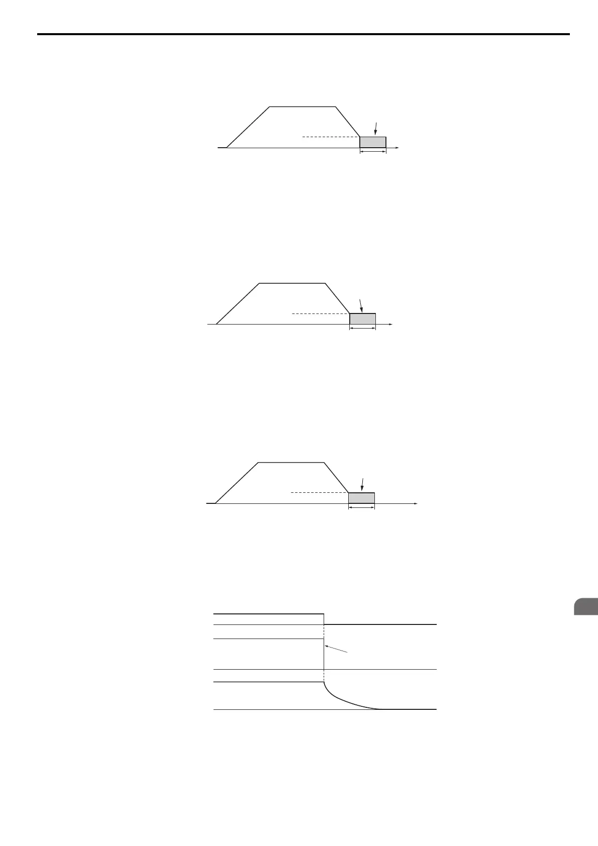
V/f, V/f w/PG and OLV (A1-02 = 0, 1, 2)
For these control modes, parameter b2-01 sets the starting frequency for DC Injection Braking at stop. Once the output
frequency falls below the setting of b2-01, DC Injection Braking is enabled for the time set in parameter b2-04.
Figure 5.3
Figure 5.3 DC Injection Braking at Stop for V/f, V/f w/PG and OLV
Note: If b2
-01 is set to a smaller value than parameter E1-09 (minimum frequency), then DC Injection Braking will begin as soon as
the frequency falls to the value set to E1-09.
OLV/PM and AOLV/PM (A1-02 = 5, 6)
For these control modes, parameter b2-01 sets the starting frequency for Short-Circuit Braking at stop. Once the output
frequency falls below the setting of b2-01, Short-Circuit Braking is enabled for the time set in parameter b2-13. If DC
Injection Braking time is enabled at stop, then DC Injection Braking is performed for the time set in b2-04 after
Short-Circuit Braking is complete.
Figure 5.4
Figure 5.4 Short-Circuit Braking at Stop in OLV/PM and AOLV/PM
Note: If b2
-01 is set to a smaller value than parameter E1-09 (minimum frequency), then DC Injection Braking will begin as soon as
the frequency falls to the value set to E1-09.
The drive will not perform short-circuit braking when b2-01 = E1-09 = 0 Hz.
CLV and CLV/PM (A1-02 = 3, 7)
For these control modes, parameter b2-01 sets the starting frequency for Zero Speed Control (not position lock) at stop.
Once the output frequency falls below the setting of b2-01, Zero Speed Control is enabled for the time set in parameter
b2-04.
Figure 5.5
Figure 5.5 Zero Speed Control at Stop in CLV and CLV/PM
Note: If b2
-01 is set to lower than the minimum frequency (E1-09), then Zero Speed Control begins at the frequency set to E1-09.
Setting 1: Coast to stop
When the Run command is removed, the drive will shut off its output and the motor will coast (uncontrolled
deceleration) to stop. The stopping time is determined by the inertia and the friction in the driven system.
Figure 5.6
Figure 5.6 Coast to Stop
Note: Af
ter a stop is initiated, any subsequent Run command entered will be ignored until the minimum baseblock time (L2-03) has
expired. Do not enter Run command until it has come to a complete stop. To start the motor back up before it has stopped
completely, use DC Injection at start (refer to b2-03: DC Injection Braking T
ime at Start on page 159) or Speed Search (refer to
b3: Speed Search on page 160).
Output
frequency
Time
b2-04
DC Injection
Braking
E1-09 Min. Frequency
b2-01 Zero Speed Level
Output
frequency
Time
b2-13
Short Circuit
Braking
E1-09 Min. Frequency
b2-01 Zero Speed Level
Output
frequency
Time
Zero Speed
Control
b2-04
E1-09 Min. Frequency
b2-01 Zero Speed Level
Drive output is shut off
Run
command
Output
frequency
Motor speed
ON OFF