5.2 b: Application
YASKAWA ELECTRIC SIEP C710616 27G YASKAWA AC Drive A1000 Technical Manual 177
b5-47: PID Output Reverse Selection 2
Determines whether a negative PID output reverses the direction of drive operation. When the PID function is used to
trim the frequency reference (b5-01 = 3 or 4), this parameter has no effect and the PID output will not be limited (same as
b5-11 = 1).
Setting 0: Reverse Disabled
Negative PID output will be limited to 0 and the drive output will be stopped.
Setting 1: Reverse Enabled
Negative PID output will cause the drive to run in the opposite direction.
Fine-Tuning PID
Once PID control parameters have been set, fine-tuning may be required. Follow the directions below.
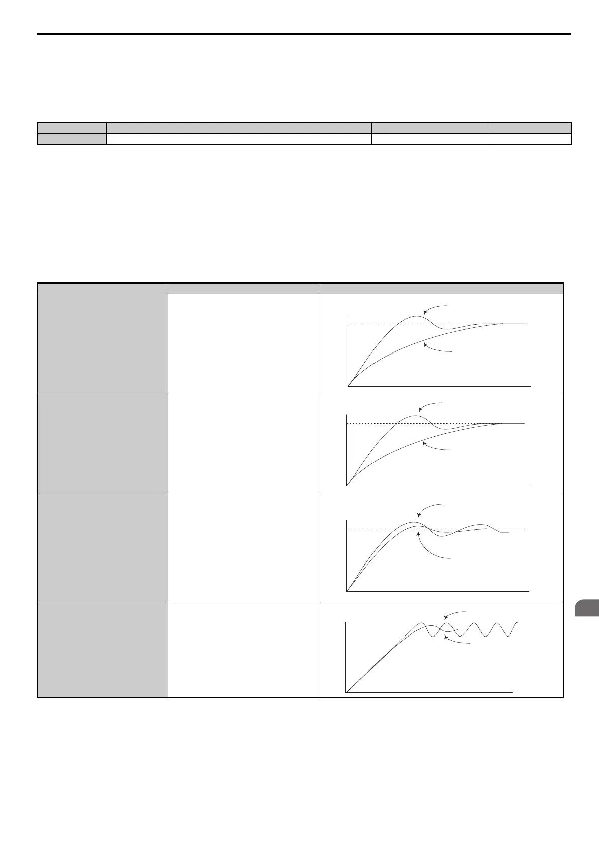
Table 5.12 PID Fine Tuning
No. Name Setting Range Default
b5-47 PID Output Reverse Selection 2 0, 1 1
Goal Tuning Procedure Result
Overshoot must be suppressed
• Reduce the derivative time (b5-05)
• increase the integral time (b5-03)
Quickly achieve stability, and some
overshoot is permissible
• Decrease the integral time (b5-03)
• Increase the derivati
ve time (b5-05)
Suppress long cycle oscillations (longer than
the integral time setting)
• Increase the integral time (b5-03)
Suppress short cycle oscillations
• If oscillation cycle time is close to the derivative
t
ime, the derivative part is likely having too much
influence. Reduce the derivative time (b5-05).
• If the derivative time is set to 0.00 s and
o
scillations are still a problem, try reducing the
proportional gain (b5-02) or try increasing the
PID primary delay time (b5-08)
Response
Before adjustment
After adjustment
Time
Response
Before adjustment
After adjustment
Time
Response
Before adjustment
After adjustment
Time
Response
After adjustment
Before adjustment
Time
 Loading...


