5.8 L: Protection Functions
276 YASKAWA ELECTRIC SIEP C710616 27G YASKAWA AC Drive A1000 Technical Manual
KEB Ride-Thru Start
KEB operation is always triggered in the same way, independent of the selected KEB operation mode. When the KEB
function is selected as the function to be executed when power loss operation occurs (L2-01 = 3, 4, or 5), then KEB
Ride-Thru will be activated if one of the following conditions becomes true:
• A digital input programmed for H1- = 65 or 66 is activated. This will start K
EB operation using the mode selected
in parameter L2-29.
• A digital input programmed for H1- = 7A or 7B is activated. This will automat
ically select Single KEB Ride-Thru
2, disregarding the setting of L2-29.
• The DC bus voltage fell below the level specified in L2-05.
The KEB operation will start as specified in L2-29.
Note: KEB Ride-Thru 1 and 2 cannot both be assigned to input terminals at the same time. Attempting this will trigger an oPE3 error.
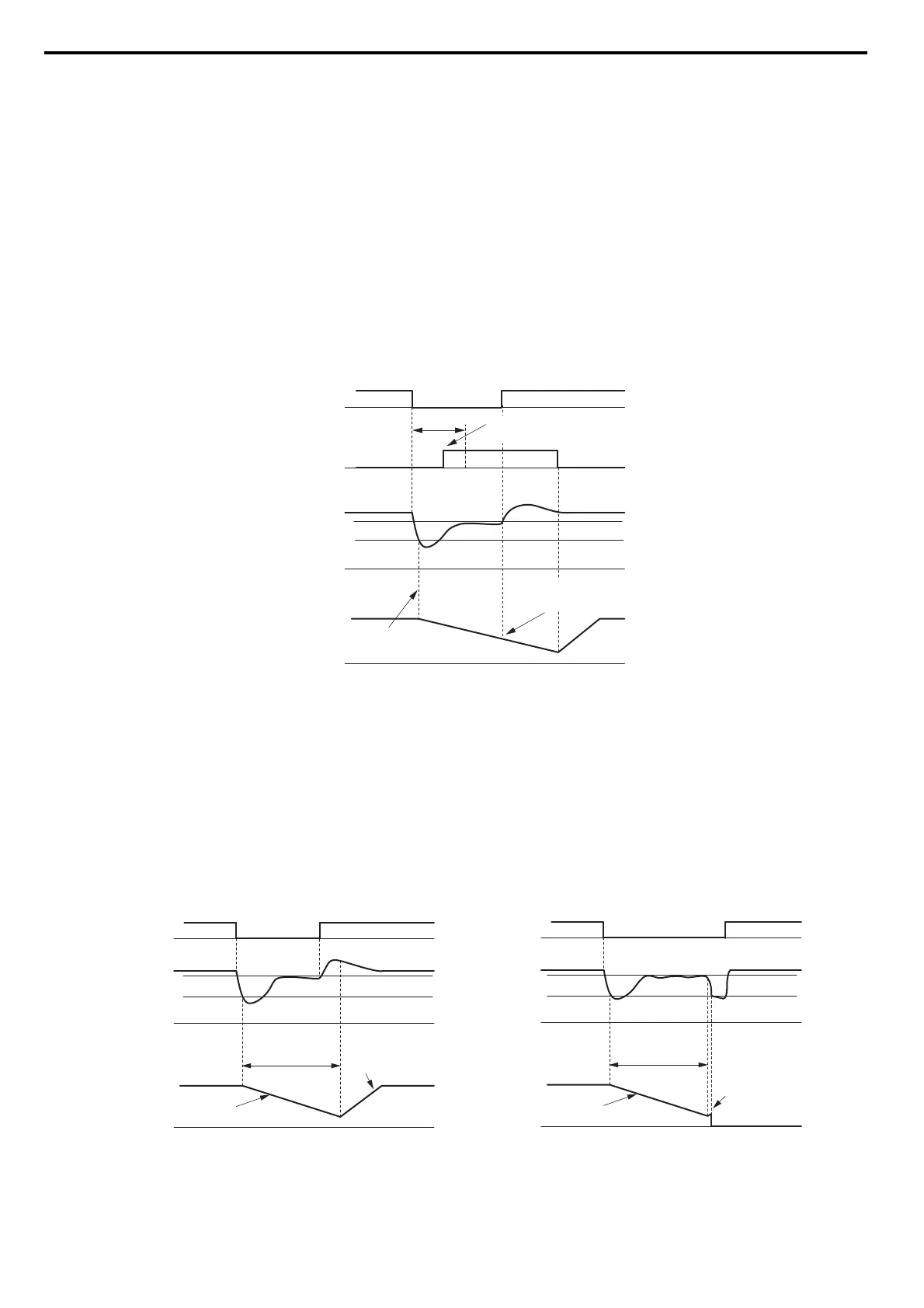
If a digital input is used for triggering the KEB operation and the device that controls the input acts relatively slow,
parameter L2-10 can be used to set a minimum KEB operation time. In the example below, KEB operation is triggered
by the DC bus voltage and the Hold command is triggered by a digital input.
Figure 5.95
Figure 5.95 KEB Operation Using a KEB Input
KEB Ride-Thru End Detection
The KEB function end detection depends on the setting of parameter L2-01 and if a digital input programmed for KEB
(H1- = 65, 66, 7A, 7B) is used or not.
KEB Ride-Thru Operation in L2-02, Input Terminals Not Used
Here, L2-01 = 3 and the input terminals have not been set for KEB Ride-Thru (H1- does not equal 65, 66, 7A, 7B).
After decelerating for the time set in parameter L2-02, the drive ends KEB operation and attempts to accelerate back to
the frequency reference. If the power has not returned within L2-02, an Uv1 fault occurs and the drive output shuts off.
Figure 5.96
Figure 5.96 KEB Operation Using L2-02, Without KEB Input
L2-05 (Uv Detection Level)
0 Hz
DC bus voltage
0 V
0 V
KEB Digital Input
Main Power Supply
Output Frequency
L2-10
KEB deceleration is
triggered by DC bus voltage
KEB digital input is
set with in L2-10
Input holds KEB operation,
even though voltage has
returned
L2-11 (Desired DC Bus Voltage)
Power loss
L2-11 (Desired DC Bus
Voltage)
L2-05 (Uv Detection Level)
L2-11 (Desired DC
Bus Voltage)
L2-05 (Uv Detection Level)
0 Hz
L2-02
(Power Loss
Ride-Thru Time)
0 V
0 V
KEB Deceleration
Acceleration using L2-07 or
C1-01/03/05/07 if L2-07 = 0
Power Loss shorter than L2-02
0 Hz
L2-02
(Power Loss
Ride-Thru Time)
0 V
0 V
KEB Deceleration
Drive attempts to restart but
power has not returned
An Uv1 fault is triggered
Power Loss longer than L2-02
Power Loss
Power Loss
DC Bus Voltage
Main Power Supply
Output Frequency
 Loading...


