6.4 Fault Detection
346 YASKAWA ELECTRIC SIEP C710616 27G YASKAWA AC Drive A1000 Technical Manual
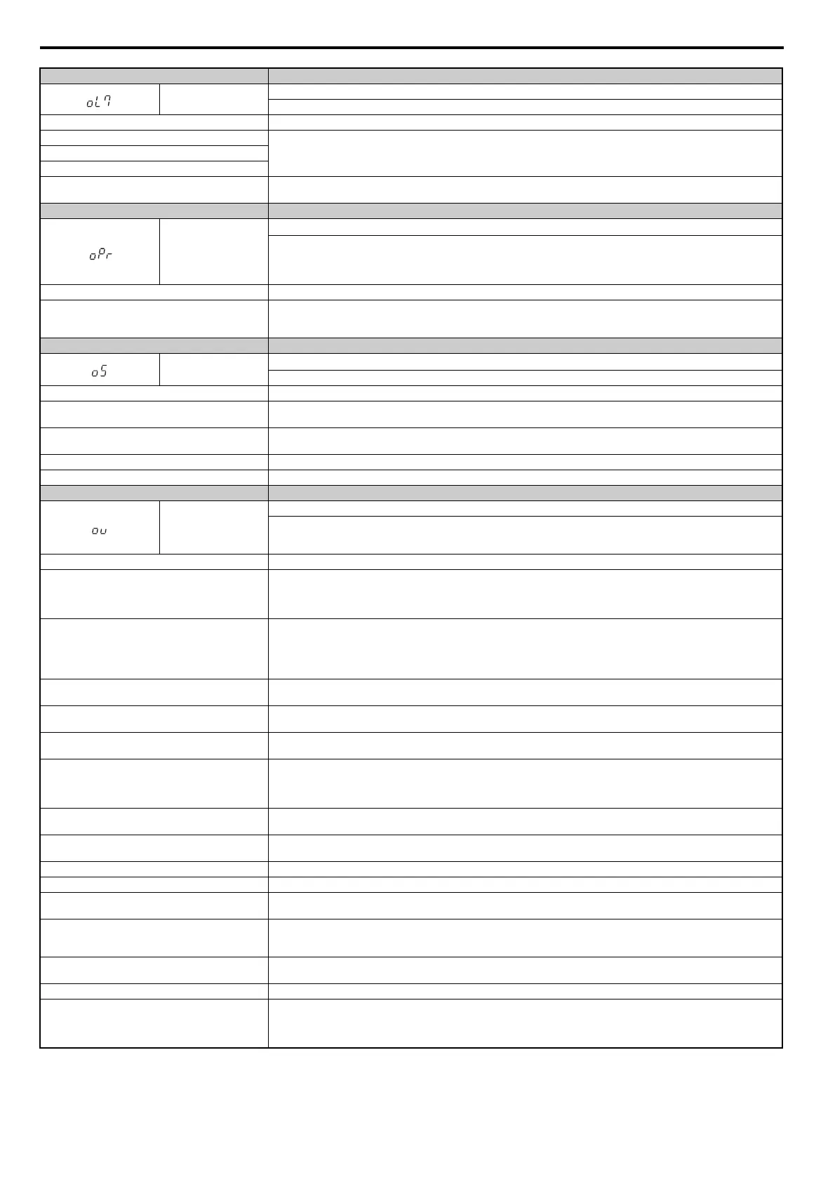
Digital Operator Display Fault Name
oL7
High Slip Braking oL
Th
e output frequency stayed constant for longer than the time set in n3-04 during High Slip Braking.
Cause Possible Solution
Excessive load inertia.
• Reduce deceleration times in parameters C
1-02, C1-04, C1-06, and C1-08 for applications that do not use High Slip Braking.
• Use a braking resistor to shorten deceleration time.
Motor is driven by the load.
So
mething on the load side is restricting deceleration.
The overload time during High Slip Braking is too short.
• Increase parameter n3-04 (High-s
lip Braking Overload Time).
• Install a thermal relay and increase the setting of n3-04 to the maximum value.
Digital Operator Display Fault Name
oPr
External Digital Operator Connection Fault
• The external operator has been di
sconnected from the drive.
Note:
An oPr fault will occur when all of the following conditions are true:
• Output is interrupted when the operator is disconnected (o2-06 = 1).
• The Run command is assigned to the operator (b1-02 = 0 and LOCAL has been selected).
Cause Possible Solution
External operator is not properly connected to the drive.
• Check the connection between the operator and the drive.
• Replace the cable if damaged.
• Turn off the drive input power and disconnect the operator. Next reconnect the operator and turn the drive input power back on.
Digital Operator Display Fault Name
oS
Overspeed
The
motor speed feedback exceeded the F1-08 setting.
Cause Possible Solution
Overshoot is occurring.
• Reduce the settings for C5-01 (Speed Control
Proportional Gain 1) and increase C5-02 (Speed Control Integral Time 1).
• If using a Closed Loop Vector mode, enable Feed
Forward and perform Inertia Auto-Tuning.
Incorrect speed feedback scaling i
f terminal RP is used
as speed feedback input in V/f control.
• Set H6-02 to the value of the speed feedback signal frequency when the motor runs at the maximum speed.
• Adjust the input signal using parameters H6-03 through H6-05.
Incorrect number of PG pulses has been set. Check and correct parameter F1-01.
Inappropriate parameter settings. Check the setting for the overspeed detection level and the overspeed detection time (F1-08 and F1-09).
Digital Operator Display Fault Name
ov
Overvoltage
V
oltage in the DC bus has exceeded the overvoltage detection level.
• For 200 V class: approximately 410 V
• For 400 V class: approximately 820 V
Cause Possible Solution
Deceleration time is too short and
regenerative energy is
flowing from the motor into the drive.
• Increase the deceleratio
n time (C1-02, C1-04, C1-06, C1-08).
• Install a dynamic braking option.
• Enable stall prevention during deceleration (L3-04 = 1).
Stall Prevention is enabled as the default setting.
Fast acceleration time causes the motor to overshoot the
speed refe
rence.
• Check if sudden drive acceleration triggers an overvoltage alarm.
• Increase the acceleration time.
• Use longer S-curve acceleration and
deceleration times.
• Enable the Overvoltage Suppress
ion function (L3-11 = 1).
• Lengthen the S-curve at acceleration end.
Excessive braking load.
Th
e braking torque was too high, causing regenerative energy to charge the DC bus. Reduce the braking torque, use a dynamic
braking option, or lengthen decel time.
Surge voltage entering from the drive input power.
Install a DC reactor.
Note: Voltage surge can result from a thyristor convertor and phase advancing capacitor using the same input power supply.
Ground fault in the output circuit causing the DC bus
capacitor to overcharge.
• Check the motor wiring for ground faults.
• Correct grounding shorts and turn the power back on.
Improper Setting of Speed Search related parameters.
(I
ncludes Speed Search after a momentary power loss
and after a fault restart.)
• Check the settings for Speed Sea
rch-related parameters.
• Enable Speed Search restart f
unction (b3-19 greater than or equal to 1, up to 10).
• Adjust the current level during Speed Search and the
deceleration time (b3-02 and b3-03 respectively).
• Perform Stationary Auto-Tuning for line-to-line resistance and t
hen enable Speed Estimation Speed Search (b3-24 = 1).
Drive input power voltage is too high.
• Check the voltage.
• Lower drive input power voltage within the limits listed in the specifications.
The braking transistor is wired incorrectly.
• Check braking transistor wiring for errors.
• Properly rewire the braking resistor device.
PG cable is disconnected. Reconnect the cable.
PG cab
le wiring is wrong. Correct the wiring.
Electrical signal interference along the PG encoder
wiring.
Separate the wiring from the source of the noise (often the output lines from the drive).
Drive fails to operate properly due to electrical signal
interference.
• Review the list of possible solut
ions provided for controlling noise.
• Review the section on handling electrical signal interference and check
the control circuit lines, main circuit lines, and ground
wiring.
Load inertia has been set incorrectly.
• Check the load inertia settings when using KEB, overvolt
age suppression, or Stall Prevention during deceleration.
• Adjust the load inertia ratio in L3-25 to better match the load.
Braking function is being used in OLV/PM. Connect a braking resistor.
Mo
tor hunting occurs.
• Adjust the parameters that control hunting.
• Set the gain for Hunting Prevention (n1-02).
• Adjust the AFR time constant (n2-02 and n2-03).
• Adjust the speed feedback detection suppression gain for PM motors (n8-45
) and the time constant for pull-in current (n8-47).

 Loading...


