xi
IM DLM6054-01EN
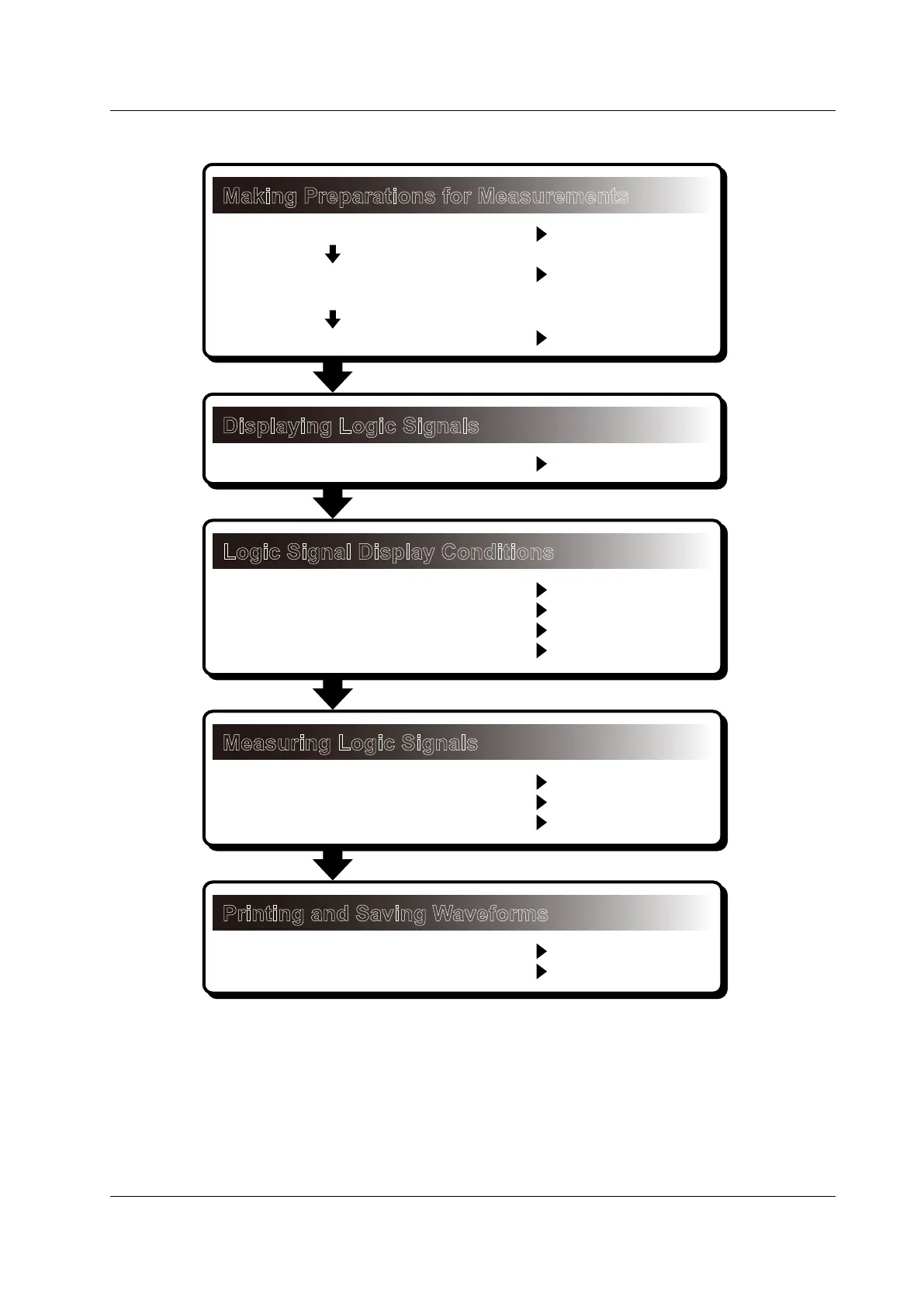
Workflow
Logic Signal Observation
Making Preparations for Measurements
Displaying Logic Signals
Logic Signal Display Conditions
Install the DL6000/DLM6000.
Connect the power supply,
and turn the power switch on.
Connect logic probes.
Turn logic signal display on.
• Display range and vertical position
• Bus and state displays
• Threshold levels
• Triggering
Measuring Logic Signals
• D/A conversion
• Cursor measurement
• Search logic signals.
Printing and Saving Waveforms
• Print screen captures.
• Save data.
Section 3.2
Section 3.3
Section 3.6
Section 5.2
Section 5.2
Section 5.2
Section 5.2
Chapter 6
Section 9.7
Section 10.1
Section 10.9
Chapter 12
Chapter 13
 Loading...


