3-14
IM DLM6054-01EN
3.6 Connecting Logic Probes
CAUTION
• The non-destructive input voltage range for logic probe input is ±40 V (DC + peak AC) or
28 Vrms on the 701980, 701981, and 701989 and ±42 V (DC + peak AC) or 29 Vrms on
the 701988. Applying a voltage greater than either of the specified limits may damage the
logic probe or the DLM6000. If the frequency is high, the DLM6000 may be damaged at
even lower voltages. For information about derating based on frequency for a particular
logic probe, see the probe’s user’s manual.
• The 8 input lines on each port have a common ground. In add
ition, the ground for the
DLM6000 and the ground for each port are also common. Do not connect inputs that have
different common voltages, as doing so may cause damage to the DLM6000, logic probe,
or other connected instruments.
• Make sure to turn of
f the power to the DLM6000 before connecting or disconnecting a logic
probe cable.
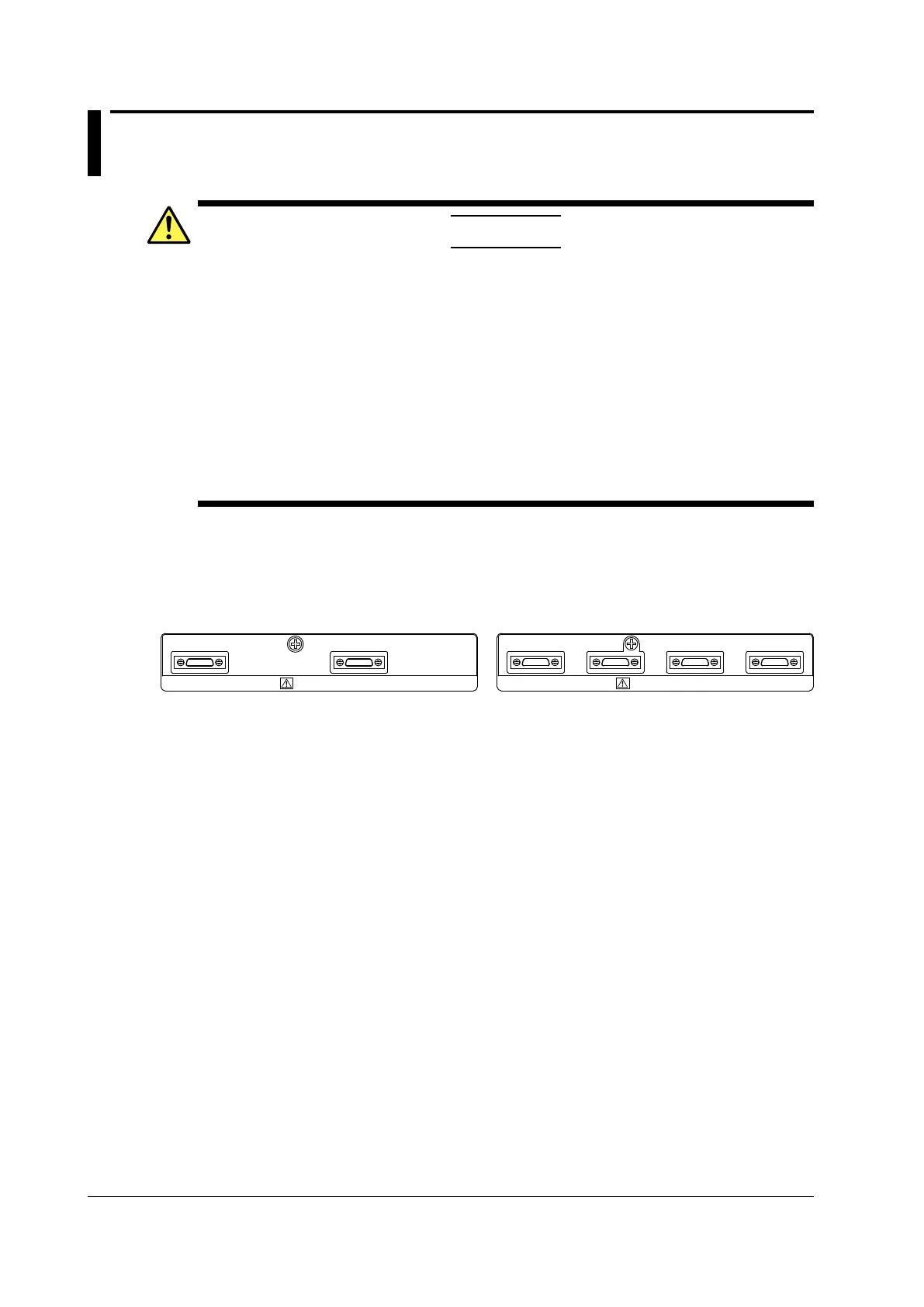
Logic Signal Input Ports
Connect the logic probe (701980/701981/701988/701989) to any of the four logic signal input ports
(POD A, POD B, POD C, and POD D) on the rear panel.
LOGIC PROBE
A B C D
LOGIC PROBE
A C
DLM6000, 16-bit model DLM6000, 32-bit model
About the Logic Probe
The logic probe (701980/701981) is designed exclusively for the logic signal input ports of the
DLM6000. Use the connection lead (accessory) to connect to the point of measurement. Do not alter
the connection lead, as it may cause the lead from satisfying the specifications.
Each port has 8 lines of logic input terminals. You can set the threshold level from the DLM6000 menu (see
section 5.2).
 Loading...


