Making Preparations for Measurements
3-13
IM DLM6054-01EN
3
2
1
4
5
6
7
8
9
10
11
12
13
14
15
16
17
18
Index
App
Explanation
Necessity of Phase Correction of the Probe
The probe comes with its phase corrected approximately to match the input capacitance of the
relevant oscilloscope. However, there is variance in the input resistance and input capacitance of
each input channel of individual oscilloscopes. This results in a mismatch in the voltage divider ratio
between low and high frequency signals and causes uneven frequency characterstics.
There is a variable capacitor for adjusting the division ratio (tri
mmer) for high frequency signals on
the probe. The phase is corrected by adjusting this trimmer so that even frequency characteristics
are obtained.
When using the probe for the first time, make sure to perform phase correction.
Because the input capacitance varies on each channel, probe
compensation is required when the
probe is switched from one channel to another.
Phase Compensation Signal
The following square wave signal is output from the signal output terminal for probe compensation
adjustment.
Frequency: Approx. 1 kHz
Amplitude: Approx. 1 V
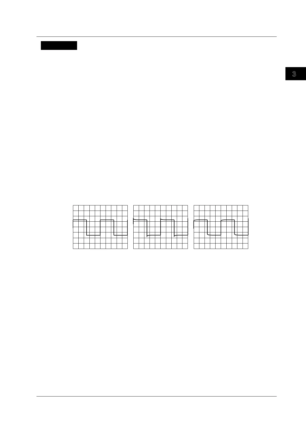
Differences in the Waveform due to the Phase Correction of the Probe
Correct waveform Over compensated (The
gain in the high-frequency
region is too high.)
(The gain in the high-frequency
region is too low.)
3.5 Compensating the Probe (Phase Correction)
 Loading...


