5-8
IM DLM6054-01EN
5.2 Vertical Axis Settings for Logic Input Signals
This section explains how to turn the bus display on and off and how to set the vertical display range,
position, grouping, threshold, and other settings of a logic input signal (LOGIC).
You can apply logic signals to the logic signal input ports (POD A, POD B, POD C, and POD D) on the
DLM6000 rear panel.
*
* On 16-bit models, the logic signal input ports are POD A and POD C.
Procedure
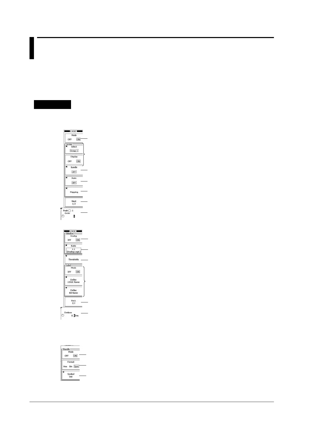
LOGIC Menu
Press LOGIC to display the first page of the following two-page menu.
Hides the logic signal area
Turn logic signal displays on and off by group.
(Set Select to choose a group and then set Display
to turn that group’s logic signal display on or off.)
Set the bus display.
Set the state display.
Configure the grouping.
Displays the second page of the menu
Set the display order.
Press the Next soft key to display the second page of the menu.
Turns simultaneous analog waveform display on and off
Set the ratio between the analog waveform area and
the logic signal area (1:3, 1:1, 3:1).
Set the threshold levels.
Set the label display.
(Set Mode to turn the label display on or off. Set Define
LOGIC Name to specify the group name. Set Define
Bit Name to specify the bit name.)
Displays the first page of the menu
Set the deskew value.
Configuring the Bus Display (Bundle)
Press the Bundle soft key to display the following menu.
Turns the bus display on and off.
(Select ON for bus display or OFF for bit display.)
Set the format (Hex, Bin, Sym).
Configure symbols (only when Format is set to Sym).
 Loading...


