9-9
IM DLM6054-01EN
Computed and Reference Waveforms
9
10
11
12
13
14
15
16
17
18
Index
App
Explanation
Taking the count starting point (Initial Point) to be zero, the DL6000/DLM6000 increments or
decrements the counter based on the phase changes in the waveforms assigned to Source1 (phase A)
and Source2 (phase B).
The DL6000/DLM6000 increments and decrements the counter depending on how phases A and B
change, treating the state when the waveform is above the specified threshold level (Threshold1 or
Threshold2) as 1 and the state when the waveform is below the threshold level as 0.
Count Conditions (Setup)
Threshold Level (Threshold1 and 2)
Set the level that the DL6000/DLM6000 uses to determine waveform state changes separately for
phases A and B.
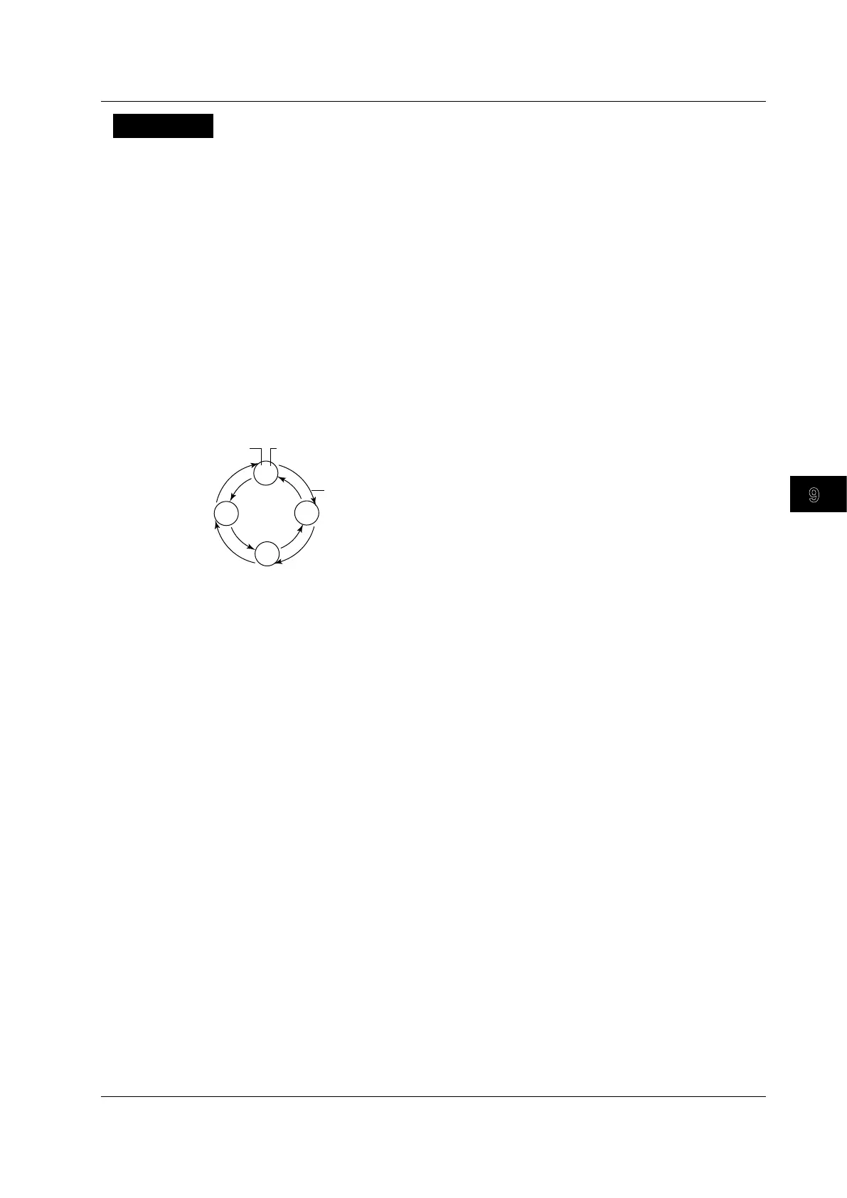
Changes in Phases A and B
As is shown below, how the counter is incremented or decremented is determined by how phases A
and B change (between the 0 and 1 states).
0 0
1 0
1 1
0 1
+1
+1
+1
+1
-1
-1
-1
-1
Direction of change
Count Start Point (Initial Point)
Specify the point to start counting at.
Selectable range: –5.00 to 5.00 divisions
Resolution: 0.01 divisions
You can also set the count start point to one of the following points (Jump to).
Trig Pos (trigger position), –5 divisions, 0 divisions, Zoom1 (the center of Zoom1), or Zoom2 (the
center of Zoom2)
9.6 Performing Rotary Counting
 Loading...


