12-19
IM DLM4038-02EN
Manual Setup
After running auto setup, you can change the following settings and display decoded results.
• Source
• Bit rate
• T Sample
• Clock tolerance
• Counter error detection
• Level used to detect source states
• Hysteresis
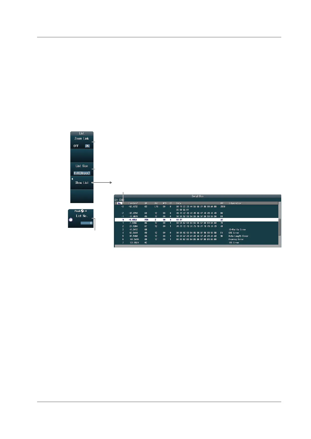
Setting the List Display (List)
Press the List soft key to display the following menu.
Set the list size and the display position
(Full Screen, Half(Upper), Half(Lower)).
Lists the analysis results
Analysis number
Turns zoom linking on or off
Set the analysis
number.
Data before the trigger position (on the left side of the waveform display) is assigned analysis numbers
in descending order (–1, –2, and so on). Data after the trigger position (on the right side of the
waveform display) is assigned analysis numbers in ascending order (0, 1, 2, and so on).
12.5 Analyzing and Searching CXPI Bus Signals (Option)
 Loading...


