1-12
IM DLM4038-02EN
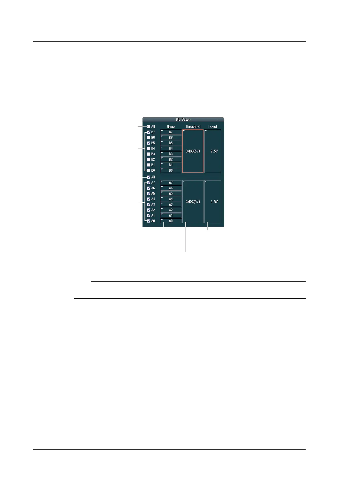
Bit Settings (Bit Setup)
Press the Bus soft key to display the following menu.
The following procedural examples use the configuration screen for when the logic probes connected
to the LOGIC(A) and LOGIC(B) ports are not 701989 and that for when the logic probes are 701989.
If different logic probes are connected to the LOGIC(A) and LOGIC(B) ports, the configuration screen
will display a combination of each probe’s settings.
When the Logic Probes Connected to A and B Are Not 701989
Set the threshold level preset (CMOS(5 V), CMOS(3.3 V),
CMOS(2.5 V), CMOS(1.8 V), ECL, Userdef).
Selecting a preset automatically sets the threshold level.
Set the threshold level.
If you change the automatically specified value,
the preset setting changes to “Userdef.”
Turn the display on or off
for B0 to B7 collectively.
Turn the display on or off
for each bit.
Turn the display on or off
for each bit.
Turn the display on or off
for A0 to A7 collectively.
Set the label for each bit.
Note
For logic probes other than the 701989, the threshold type is All and the ThresholdType setting does not
appear.
1.3 Setting the Vertical Axis for 16-bit LOGIC(A|B) (Option)
 Loading...


