1-13
IM DLM4038-02EN
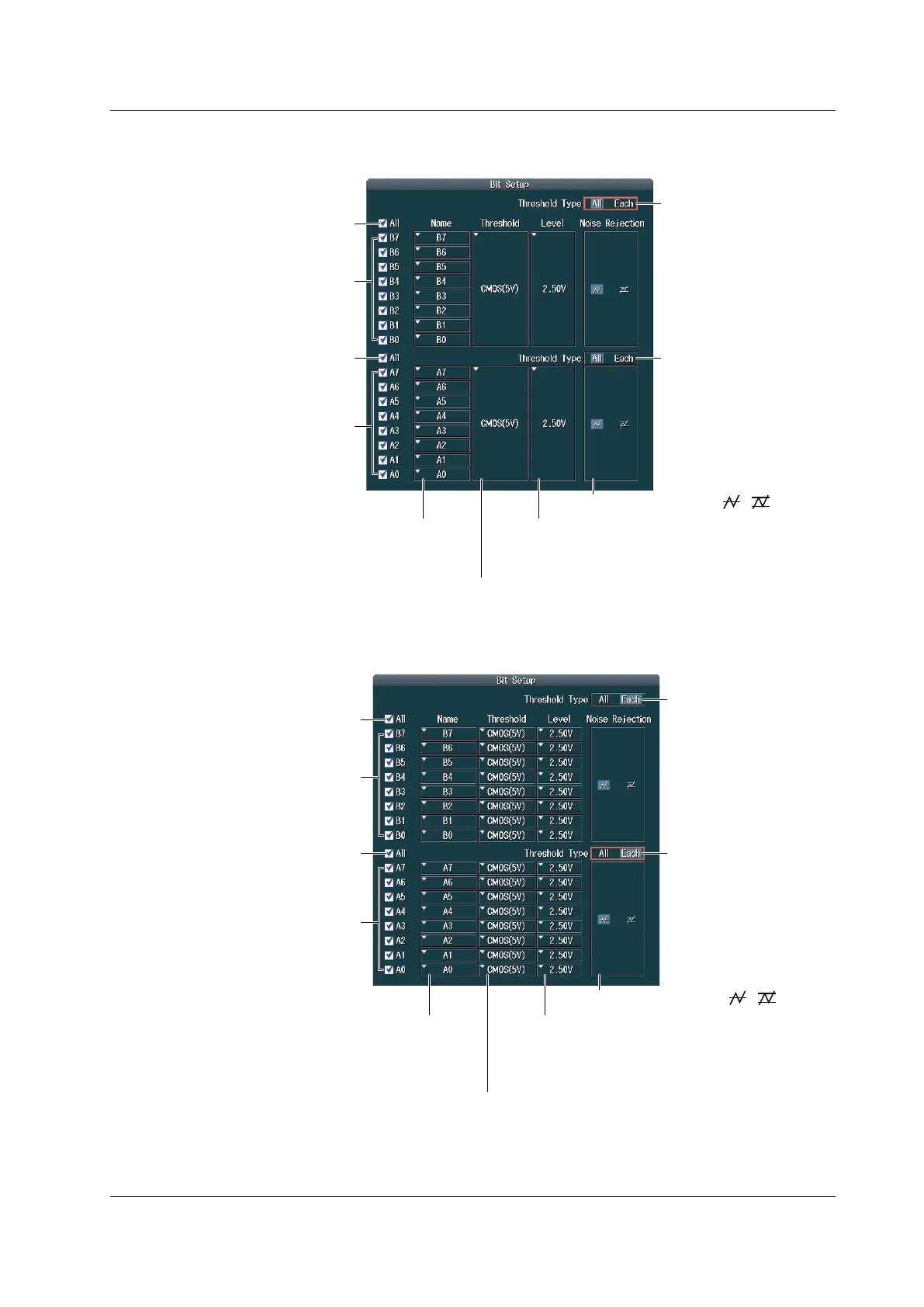
When the Logic Probes Connected to A and B Are 701989
• When the Threshold Type is All
Set the threshold level preset (CMOS(5 V), CMOS(3.3 V),
CMOS(2.5 V), CMOS(1.8 V), ECL, Userdef).
Selecting a preset automatically sets the threshold level.
Set the threshold level.
If you change the automatically specified value,
the preset setting changes to “Userdef.”
Turn the display on or
off for B0 to B7
collectively.
Turn the display on
or off for each bit.
Turn the display on
or off for each bit.
Turn the display on or
off for A0 to A7
collectively.
Set the label for each bit.
Set the threshold type of
B0 to B7 to All.
Set the threshold type of
A0 to A7 to All.
Set the noise rejection ( , ).
• When the Threshold Type is Each
Set the threshold level preset (CMOS(5 V), CMOS(3.3 V),
CMOS(2.5 V), CMOS(1.8 V), ECL, Userdef).
• Set the threshold level for each bit.
• Selecting a preset automatically sets the threshold level.
Set the threshold level.
• Set the threshold level for each bit.
• If you change the automatically specified value,
the preset setting changes to “Userdef.”
Set the noise rejection ( , ).
Turn the display on or
off for B0 to B7
collectively.
Turn the display on
or off for each bit.
Turn the display on
or off for each bit.
Turn the display on or
off for A0 to A7
collectively.
Set the label for each bit.
Set the threshold type of
B0 to B7 to Each.
Set the threshold type of A0
to A7 to Each.
1.3 Setting the Vertical Axis for 16-bit LOGIC(A|B) (Option)
 Loading...


