28 Oct
1997 21:57
CELL-DYN
®
3/35 Sample Loader TS Guide 9140234B-June 1997
VERIFICATION PROCEDURES
VP - 6.2 Mixing Head Position Adjustment
3 - 86
3
Search
Book TOC
Go Back
d. Ti
hten hardware.
G Loader
a. While Tube is Rotatin
, loosen Mixin
Paddle Assembly bracket screws (Fi
ure 3-43,
Pa
e-3-88) and adjust Assembly to center tube in rack. Ti
hten hardware.
5. Go to “VP - 6.3 Mixin
Home Sensor Check/Adjustment” (Pa
e 3-89).
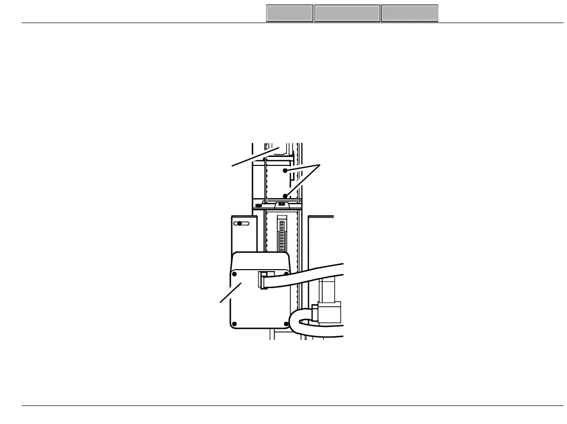
Figure 3-41 Back of Sample Loader
SL-242
(2) Ball Slide
Screws
Paddle
Motor
Tower Rear View
Barcode
Reader