46
S:\Hp8960\E1962B CDMA 2000\Pi Release\Reference Guide\Chapters\cdma2000_meas_codechan_desc.fm
Code Channel Timing and Phase Measurement Description
Code Channel Timing and Phase Measurement Description
How is a Code Channel Timing and Phase measurement made?
This measurement is designed to analyze signals that contain a reverse pilot channel. A call must be
connected with one of the following radio configurations selected:
• Fwd3, Rvs3
• Fwd4, Rvs3
• Fwd 5, Rvs4
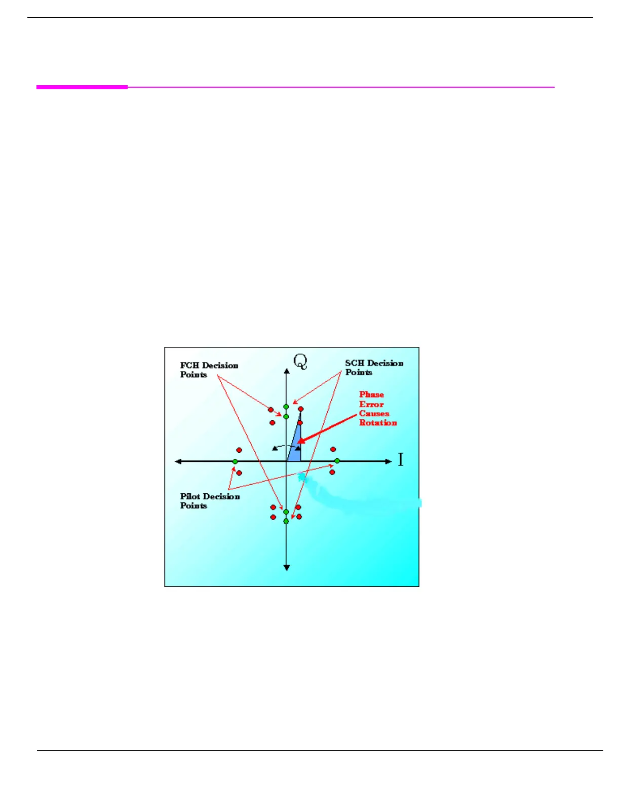
Each code channel timing and phase measurement tests the time and phase alignment of each code channel
relative to the reverse channel pilot signal. The time error returns any offset, in nanoseconds, that is detected
between the coding of each Walsh channel and the reverse channel pilot. The phase error measurement
determines whether there is any phase difference, as shown in Figure 1., that would cause a rotation in the I/Q
constellation away from the decision points.
Figure 1. I/Q Constellation Showing Phase Error
Code channel time/phase error measurements are made by sampling the down-converted input signal, then
applying DSP (Digital Signal Processing) techniques to determine the original data input to the mobile station
transmitter’s Walsh spreading function for each channel. The DSP then generates a representation of what
the “ideal” signal would be given the coding and data in use at the time of transmission. The ideal waveform is
then compared with the waveform being measured to determine code channel time error and phase error.
A Code Channel Time/Phase Error display is shown below.

 Loading...


