50
S:\Hp8960\E1962B CDMA 2000\Pi Release\Reference Guide\Chapters\cdma2000_meas_codechan_desc.fm
Code Channel Timing and Phase Measurement Description
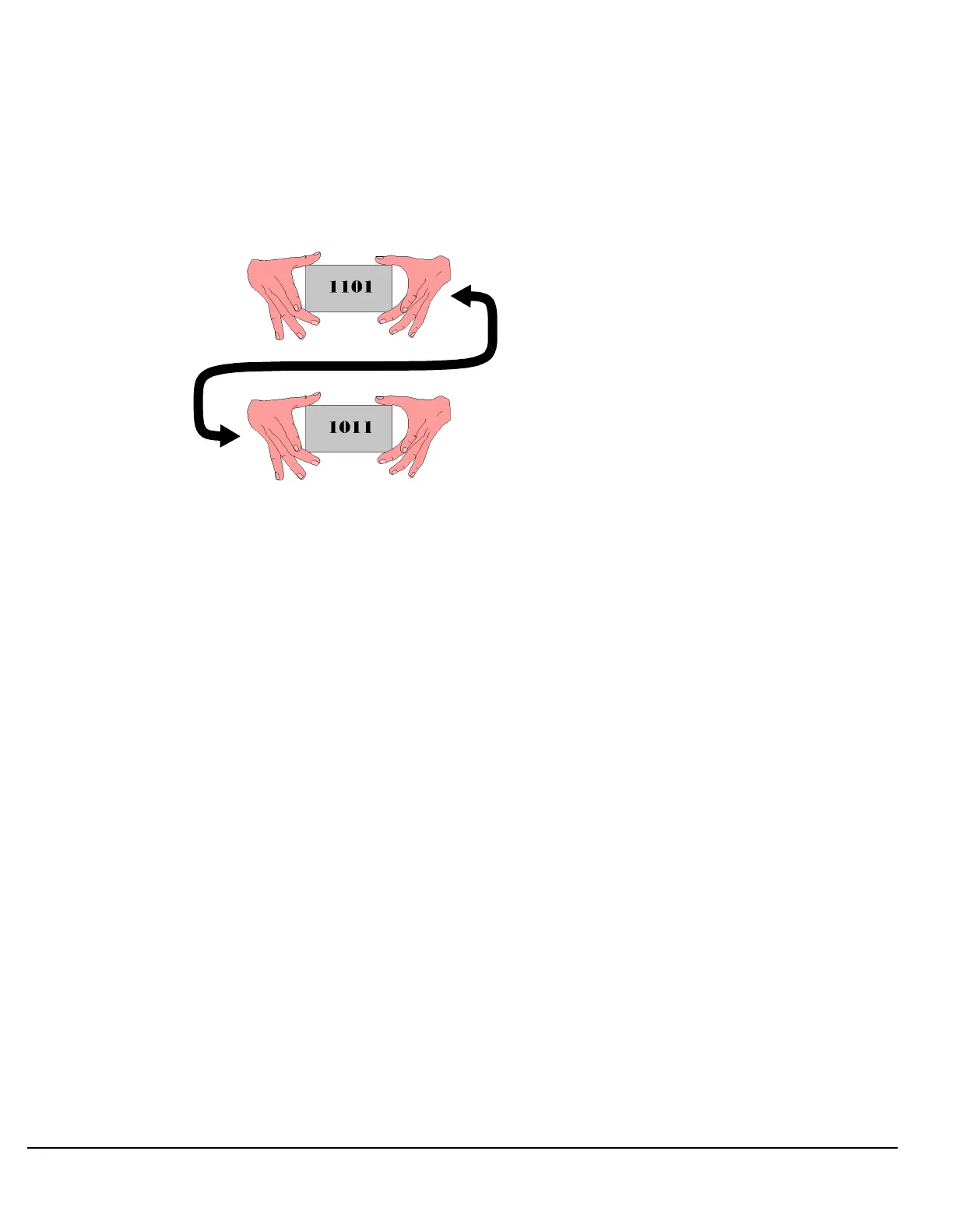
An example of bit reversal is shown in Figure 4. Bin 13 has a binary coded decimal value of 1101. If you
reverse that sequence, the result is 1011. When 1011 is converted back to a decimal value, the result is Walsh
code 11.
Figure 4. Walsh Channel Bit Reversal
Measurement Behavior
Bin 0 corresponds with Walsh will always return zero for Time Error zero and phase error because all other
measurements are relative to the pilot channel, which is located at Walsh 0, bin 0.
Input Signal Requirements
The Code Channel Timing and Phase measurement meets or exceeds specifications when the following
requirements are met:
• The frequency of the signal being measured must be in the range of 412 MHz to 483 MHz, 800 MHz to 960
MHz, or 1.7 GHz to 2.0 GHz, and within 100 kHz of the expected frequency.
• The signal level into the test set’s RF IN/OUT connector must be in the range of -25 dBm to +37 dBm, and
within 9 dBm of the expected input power (see “RFANalyzer:AUTO:POWer[:SELected]?” ) to meet
specifications.
Related Topics
“Programming a Code Channel Time/Phase Measurement”
“SETup:CCTPhase”
“FETCh:CCTPhase”
“INITiate”
“READ”
“ABORt”
“Test Adherence to Standards”
“Code Channel Time/Phase Error Measurement Troubleshooting”
Bin 13
=
Walsh 11

 Loading...


