Commonly Used Procedures 6
Agilent Nano Indenter G200 User’s Guide 6-26
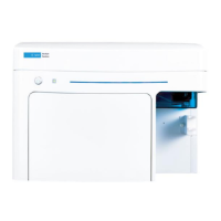
As shown in Figure 6-37, the locking pins are installed at right angles to
each other.
Figure 6-37Insert locking pins at 90 degrees
2 Place two locking pins through the collar (bottom cover) and
indenter shaft by gently inserting them through the collar and shaft
with a twisting motion, using minimal force. If the first locking-pin
hole is difficult to penetrate, try the other hole first.
3 After inserting the locking pins, click OK in the Change Indenter Tip
dialog box, shown in
Figure 6-36 on page 6-25.
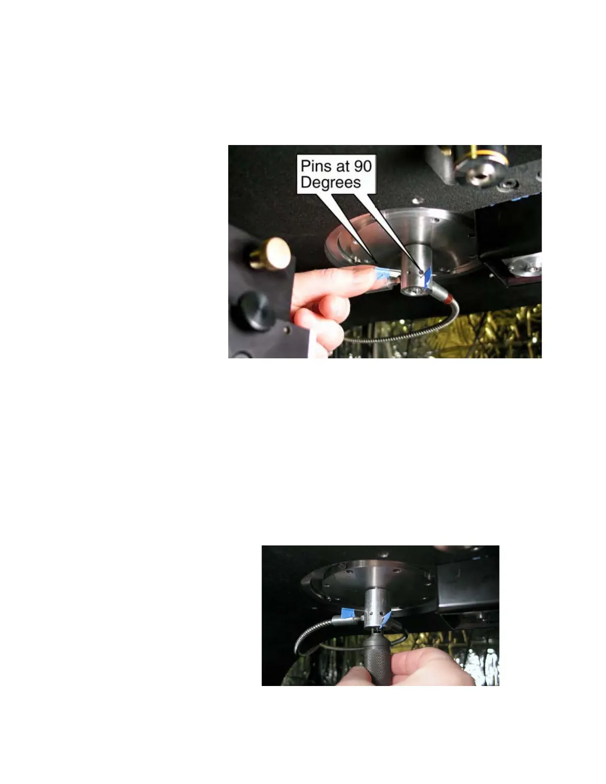
4 Gently dock the Tip-Change Tool with the Tip-Retaining Nut so that
the retaining nut fits between the remover flats, illustrated in
Figure 6-38.
Figure 6-38Alignment of indenter shaft, tip and retaining nut

 Loading...