Dynamic Contact Module II B
Agilent Nano Indenter G200 User’s Guide B-14
8 To install the new tip in the DCM II head reverse the above steps.
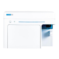
9 When you have reached the point of screwing the new tip into the
head, slowly rotate the micro-socket wrench clockwise
(
Figure B-20).
Ensure a snug fit; DO NOT over-tighten.
Figure B-20Turn wrench clockwise to screw in new tip
10 Remove the bottom-most locking pin.
11 Remove the top-most locking pin.
If the tip is not calibrated, follow the “Determining the Indenter Area
Function – DCM II” procedure.
If the tip has been calibrated, then:
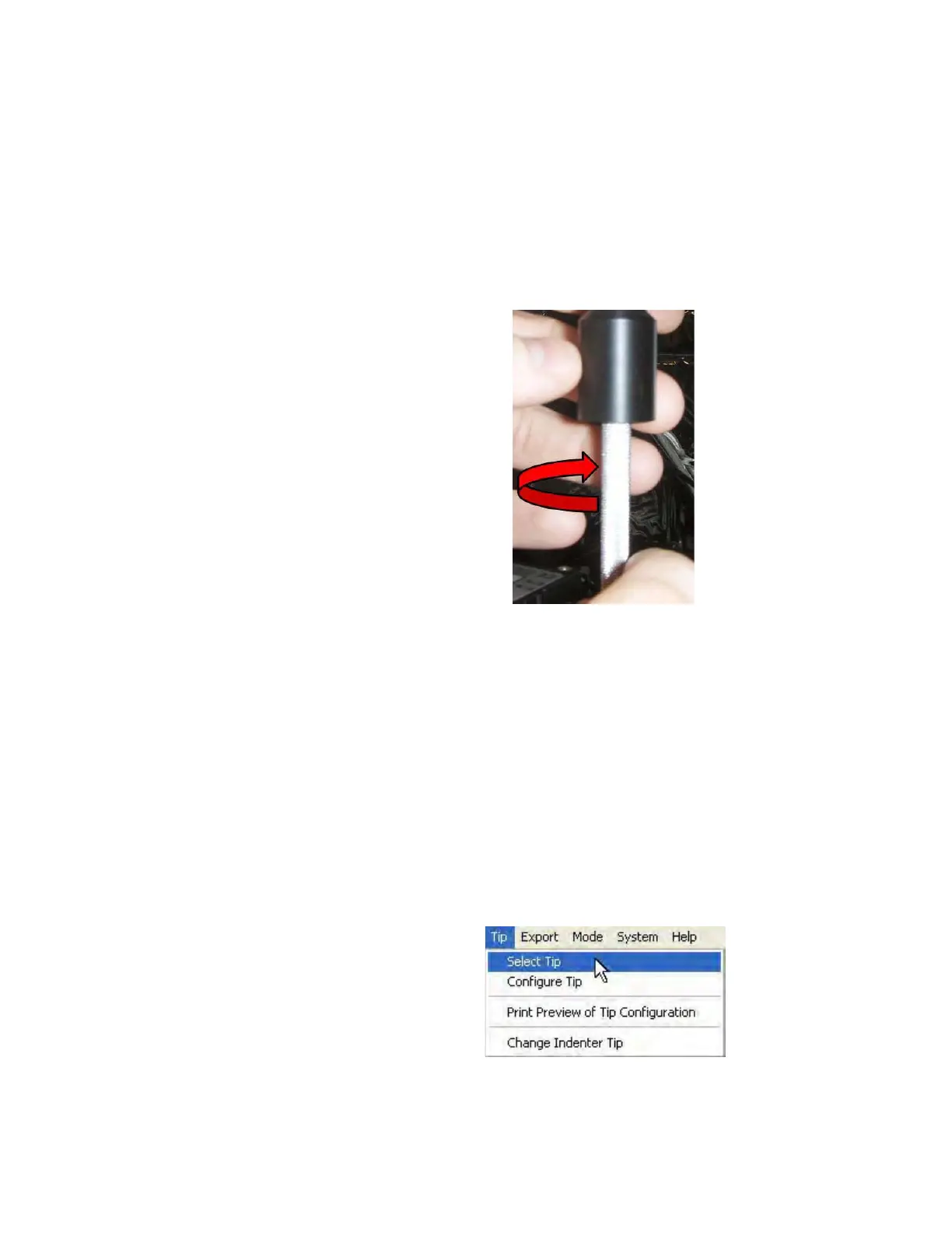
1 Select Select Tip from the Tip menu, as shown in Figure B-21.
Figure B-21Select Tip command on Tip menu

 Loading...