AIXTRON - Dokumentation CONFIDENTIAL 77
3
crius_II_en_00, Edition 06/2010
System Manual Description
CRIUS II Gas system
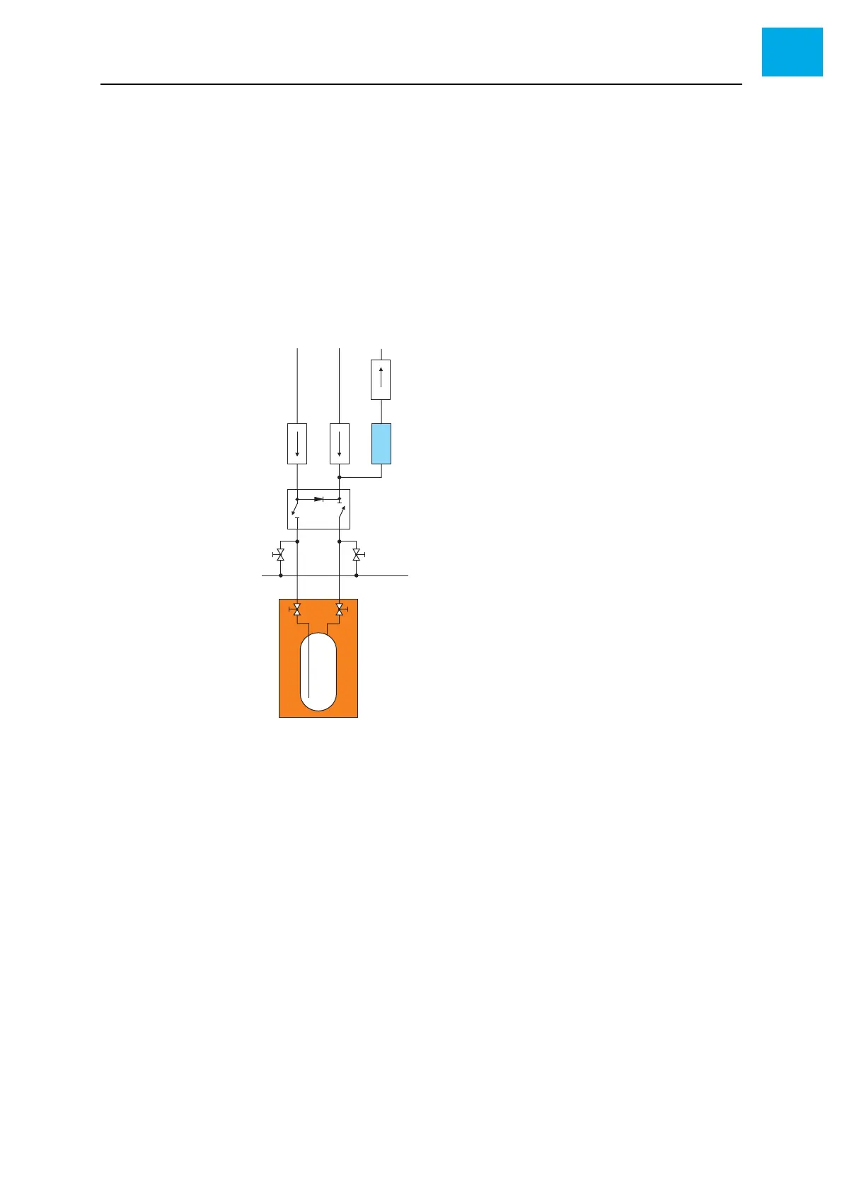
Standard MO source Fig. 3-25, 77 shows the gas diagram for the standard MO source.
The 4/2-way valve (item G) has two operating states:
Switching position: Carrier gas flows through the MO bubbler
Initial position: Carrier gas passes the MO bubbler
The source MFC (item D) controls the carrier gas flow into the bubbler. The
push MFC (item E) adds further carrier gas to dilute the carrier gas from the
bubbler.
The pressure controller (item C) controls the pressure in the bubbler.
Fig. 3-25 Standard MO source
AH
2
supply
B To MO run/vent line
C Pressure controller
D Source MFC
E Push MFC
F Measuring device for gas concentrations
(optional)
G 4/2-way MO source valve
H Quarter turn manual valve
I MO vacuum (for changing the MO bubbler)
J Manual valve at the bubbler
K Thermostat heat bath
L MO bubbler