Chapter 4 INTERFACE SETTINGS
187
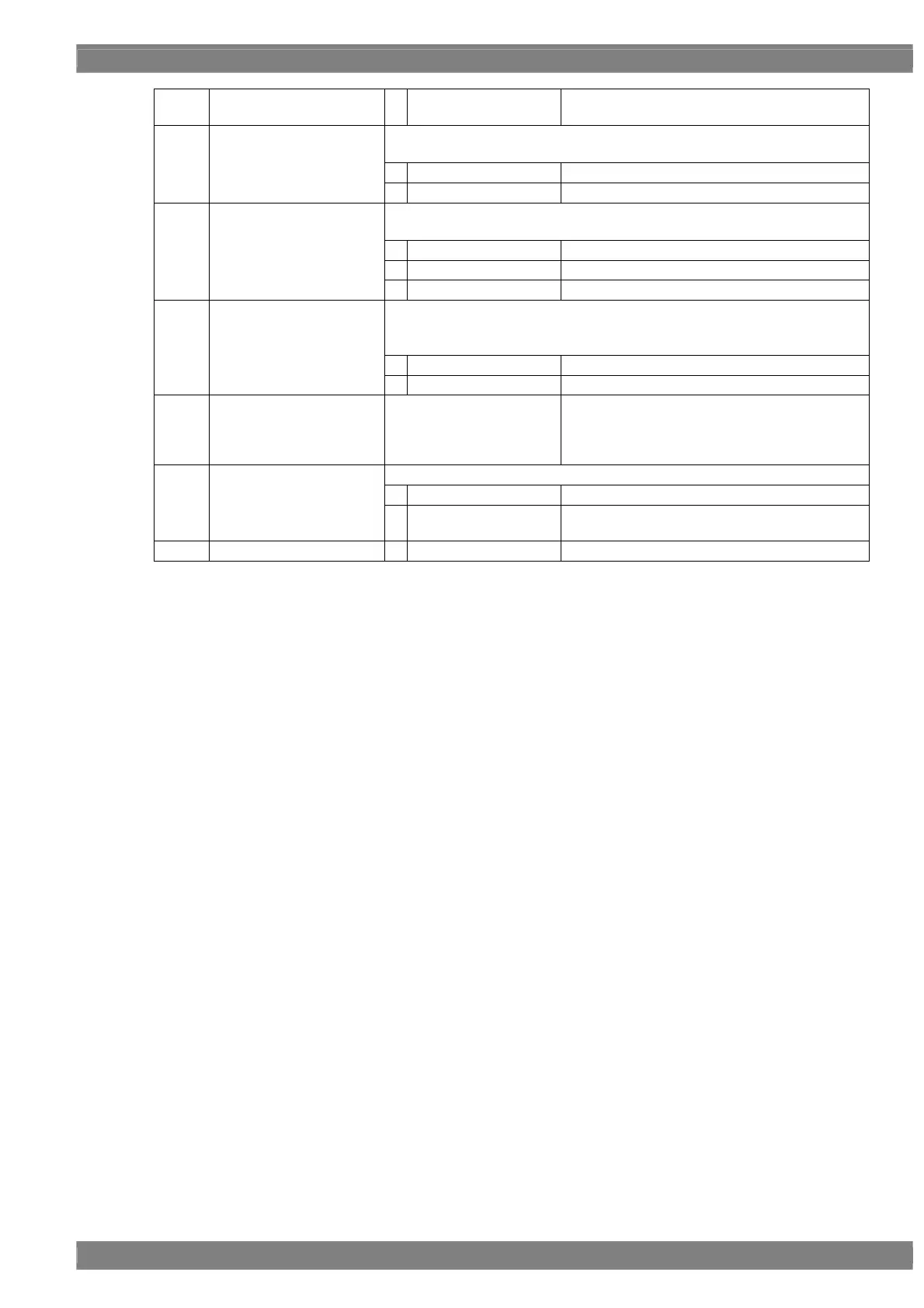
1
Manual
Output accords with the settings of items (7) and
(8).
* This parameter can be set when Link Set Mode is “Manual”.
This sets the link rate.
0
HBR(2.7Gbps)
Output at the link rate “HBR (2.7 Gbps)”
(9)
Link Rate (0/1)
1
RBR(1.62Gbps)
Output at the link rate “RBR (1.62 Gbps)”
* This parameter can be set when the Link Set Mode is “Manual”.
This sets the number of output lanes.
0
1lane
Output on 1 lane
1
2lanes
Output on 2 lanes
(10)
Number of Lane (0-2)
2
4lanes
Output on 4 lanes
This sets SSC (Spread Spectrum Clock).
Note) This item is displayed only for the unit with VM-1820A or VM-1826.
Default setting is Enable.
0
Disable
SSC is not valid
(11)
SSC (0/1)
1
Enable
SSC is Valid (Default)
(12)
Nvid 1-1667216
This sets the Nvid value.
* The Mvid value is automatically
calculated from the dot clock and the
Nvid value.
This sets the Hotplug detection status.
0
OFF
Hotplug is ignored.
(13)
HPD Mode (0/1)
1
ON
Hotplug is judged according to the status of the
connected component.
(14)
InfoFrame
 Loading...