Chapter 4 INTERFACE SETTINGS
189
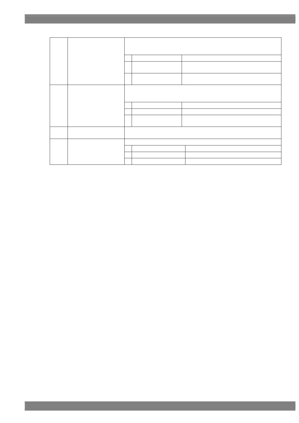
<Program fixed setting parameters>
This selects the Link Set Mode setting method.
For further details, refer to “<DP unit setting parameters> ‘Link Set Mode’” in
this section.
0
refer Program
The setting accords with the program setting.
1
Auto
Output always accords with the DPCD of the
sink component.
(1)
Link Set Mode (0-2)
2
Manual
Output always accords with the Link Rate and
Number of Lane set by the program.
This selects the Hotplug detection method.
For further details, refer to “<DP unit setting parameters> ‘HPD Mode’” in this
section.
0
refer Program
The setting accords with the program setting.
1
OFF
Hotplug is always ignored.
(2)
HPD Mode (0-2)
2
ON
Hotplug is always judged according to the status
of the connected component.
(3)
Auto Select (0/1)
This selects InfoFrame sending method.
Refer to 4.12.9 InfoFrame.
This selects SSC (Spread Spectrum Clock) setting.
0 Refer Program Follow program setting
1 Disable SSC is always not valid.
(4)
SSC (0-2)
2 Enable SSC is always valid.
 Loading...