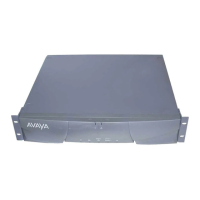
SNC-BD (Switch Node Clock Circuit Pack)
Issue 1 May 2002
8-1385555-233-143
The SNC circuit packs are associated with three MOs:
■ The ‘‘SNC-BD (Switch Node Clock Circuit Pack)’’ MO covers general SNC
board errors and errors with the serial communication channel between the
active and standby SNCs.
■ The ‘‘SNC-LINK (Switch Node Clock Link)’’ MO covers errors between the
active SNC and SNIs over the serial channel (aux data is 1). Also, the
SNC-LINK MO covers TPN Link errors between the active SNC and SNIs
(aux data is 2).
■ The ‘‘SNC-REF (Switch Node Clock Reference)’’ MO covers errors the
active SNC detects with SNI reference signals.
SNC circuit packs are part of port-network connectivity (PNC). For background
information about PNC, refer to the Maintenance Architecture and Hardware
Configurations chapters.
Figure 8-79. A Center Stage Switch Configuration
Online Switcher (OLS) power supply
carrier
EI
PPN
21
EI
EPN
EI
EPN
EI
EPN
EI
EPN
EI
EPN
EI
EPN
EI
EPN
EI
EPN
EI
EPN
EI
EPN
EI
EPN
EI
EPN
EI
EPN
EI
EPN
EI
EPN
20 18 17 16 15 14 13 12 11 10 9 8 7 6 5 4 3 2 1
** = A DS1C circuit pack may reside in this slot
Switch Node Clock (SNC) TN572
Switch Node Interface (SNI) TN573
Expansion Interface (EI) TN570
DS1 Converter (DS1C) TN574
OLS OLS
* = An EI or a DS1C circuit pack may reside in this slot
* * *
S
N
C
S
N
C
S
N
I
S
N
I
S
N
I
S
N
I
S
N
I
S
N
I
S
N
I
S
N
I
S
N
I
S
N
I
S
N
I
S
N
I
S
N
I
S
N
I
S
N
I
S
N
I
19 slot number
fiber
links
switch
node

 Loading...


