Description of the Software Modules and Parameters
Parameter manual b maXX BM3000
Document no.: 5.12001.07
103
of 820
4
is reached. A multiple of 6 is preferred for K
pf
because of the 60° symmetry of the
three-phase system or of the voltage in the voltage space vector. Typically the
K
pf
= 18 is selected to provide a good quality.
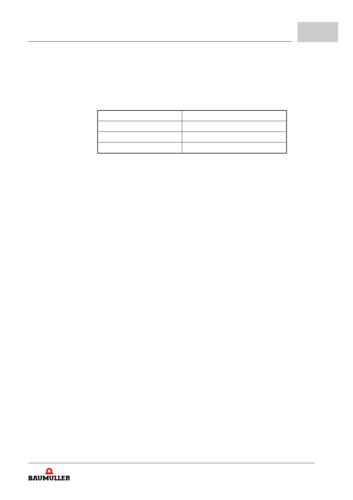
n The adjusting range is determined as follows (see chapter "Electrical data" in the in-
struction handbook of the device.
*) 900 Hz are technically (from the control point if view) possible
n The controller specifies an upper limit for the output frequency of 599 Hz so that the
900
Hz, which are technically possible, may not be reached (for details over this limit
refer to the relevant Baumüller sales department. Key word: Export limitation).
n The converter can generate output voltages with frequencies between f
max
and
599
Hz and the controller permits them. The quality of these voltages can't be guar-
anteed.
Change of the PWM frequency during operation
Up to Firmware version V01.08 the parameter can be changed only when the drive is in-
hibited. From firmware version V01.09 the parameter >130.15< can be changed during
continuous operation by the user. However, there are a few limitations:
m For applications with high demands on the performance (e.g. synchronous operation)
the complexity of the controller setting with variable current controller band width would
be too high. For this reason the PWM switching in enabled operation is restricted to the
speed control and current control operating modes (see
Z109.2–).
m The current controller cycle time may not exceed the RT0 cycle time Z1.8–. The value
will not be accepted if this condition is violated by writing a PWM frequency during the
continuous operation.
m The power unit peak current Z6.25–, depending on the PWM frequency, limits the
maximum drive current Z19.6–. If a higher PWM frequency is entered at continuous
operation, it could happen that Z19.6– should be reduced. In this case the change of
the PWM frequency is rejected. However, the change is allowed in the inhibited state
and
Z19.6– is limited automatically.
m If the PWM frequency is changed in continuous operation with activated dead time
compensation (Dead time compensation factor
Z47.50– > 0%) the adaption of the
dead time compensation must be activated after the PWM frequency Z123.1– bit 3 = 1
and therefore the values of the dead time correction table Z123.15– should be mea-
sured in this mode.
m The switching of the PWM frequency in continuous operation isn't permitted for the
sensorless synchronous motor.
m The PWM frequency should not be changed during the flying restart of the sensorless
asynchronous motor.
The failures at the implementation of the PWM switching during the continuous operation
in the controller were minimized - however, with reference to control engineering, they
Current controller cycle time Output frequency adjusting range
250 µs 0 - 225 Hz
125 µs 0 - 450 Hz
62,5 µs 0 - 599 Hz (900 Hz) *)