Description of the Software Modules and Parameters
Parameter manual b maXX BM3000
Document no.: 5.12001.07
353
of 820
4
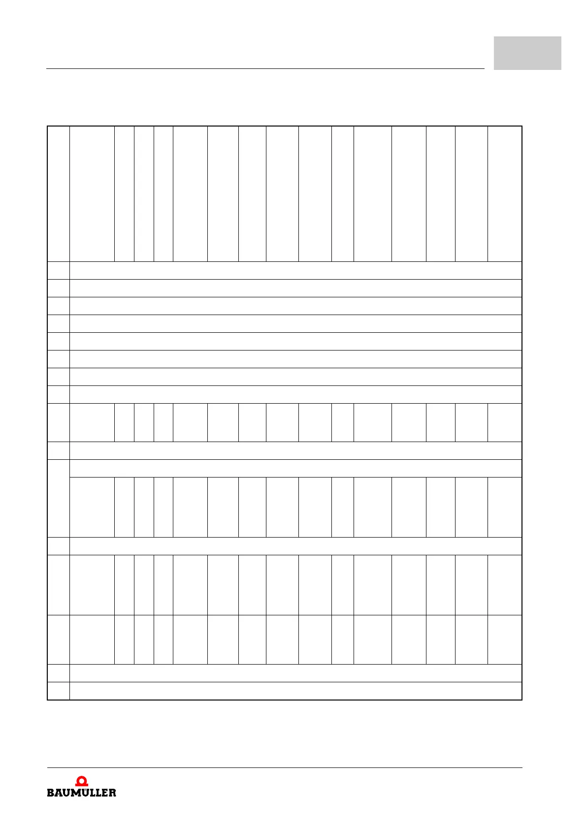
Status Word 1: General Overview of All Operating Modes
The bits labeled X are reserved and must not be evaluated by the controller.
Bit
Coupled operation (-12)
U-f operation (-10)
Voltage Setting (-9)
Current Setting (-8)
Autotuning (-7)
spindle positioning (-6)
Synchronous Operation (-5)
Position
Control (-4)
Speed Control (-3)
a)
Current Control (-2)
Notch Position Search (-1)
Target Position Setting (1)
Speed Setting 1 (2)
Manual Drive Operation (5)
Reference Run Operation (6)
0 Ready to switch on (State machine device control)
1 Switched on (State machine device control)
2 Operation enabled (State machine device control)
3 Error (State machine device control)
4 Voltage inhibited (State machine device control)
a)
)
5 Quick Stop active (State machine device control)
a
)
6 Switch-on inhibit (State machine device control)
7 Warning
8
Curve
ready
X X X X X X X
Ramp
FG
stop
X X X
Ramp
FG
stop
X X
9 Remote
10 Set value reached
Drive fol-
lows curve
X X X
Auto-
tuning
com-
plete
in posi-
tion
Posi-
tion
set
value
Posi-
tion set
value
Speed
set
value
X
Notch
position
deter-
mined
Target
position
Speed
set
value
Jog-
ging
speed
Refer-
ence
run
com-
plete
11 Internal limits active
12
Sequence
changed
X X X X
Start-
Com-
mand-
Ackno
wledge
X
Target
posi-
tion
effec-
tive
Speed
= 0
X X
Set
Value
acknowl
edg-
ment
Speed
= 0
X
Refer-
ence
run
com-
plete
13
Gear fac-
tor receipt
Refer-
ence
run
error
14 Can be set via Parameter 108.9, 108.10
15 Can be set via Parameter 108.11, 108.12
a)
These bits are active low