INSTALLATION AND STARTUP
1MANUL220 Belanger, Inc.® * PO BOX 5470. * Northville, MI 48167-5470 * Ph (248) 349-7010 * Fax (248) 380-9681 6-1
Chapter 6 Treadle Assembly
Treadle Assembly
The Treadle and the “Y” Section must be bolted together first.
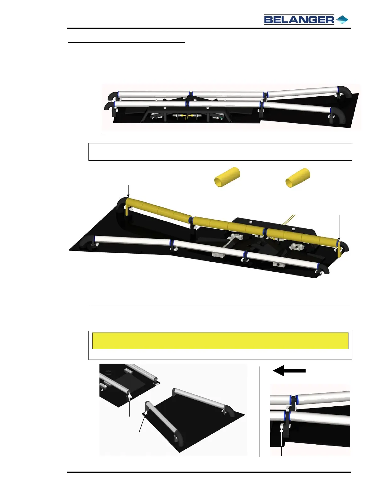
1) Lay the Treadle and the “Y” Section on a flat surface, in line with each other. See the image below.
Note: If you have purchased the Plastic Sleeve option, slide them into place now. See the image
below.
Optional Plastic Rollers
2) Remove the ends of the roller assemblies, slide the Plastic Rollers on and reassemble. Per each side there are 11 straight
rollers and 1 tapered roller. The tapered roller goes on the entrance side as shown above.
3) Secure the two sections together by aligning the stainless-steel Treadle Axles to the female holes in the “Y” Section
(vertical) mounts as shown below.