INSTALLATION AND STARTUP
6-2 Belanger, Inc. ®* PO BOX 5470. * Northville, MI 48167-5470 * Ph (248) 349-7010 * Fax (248) 380-9681 1MANUL220
Chapter 6 Treadle Assembly
Treadle Assembly
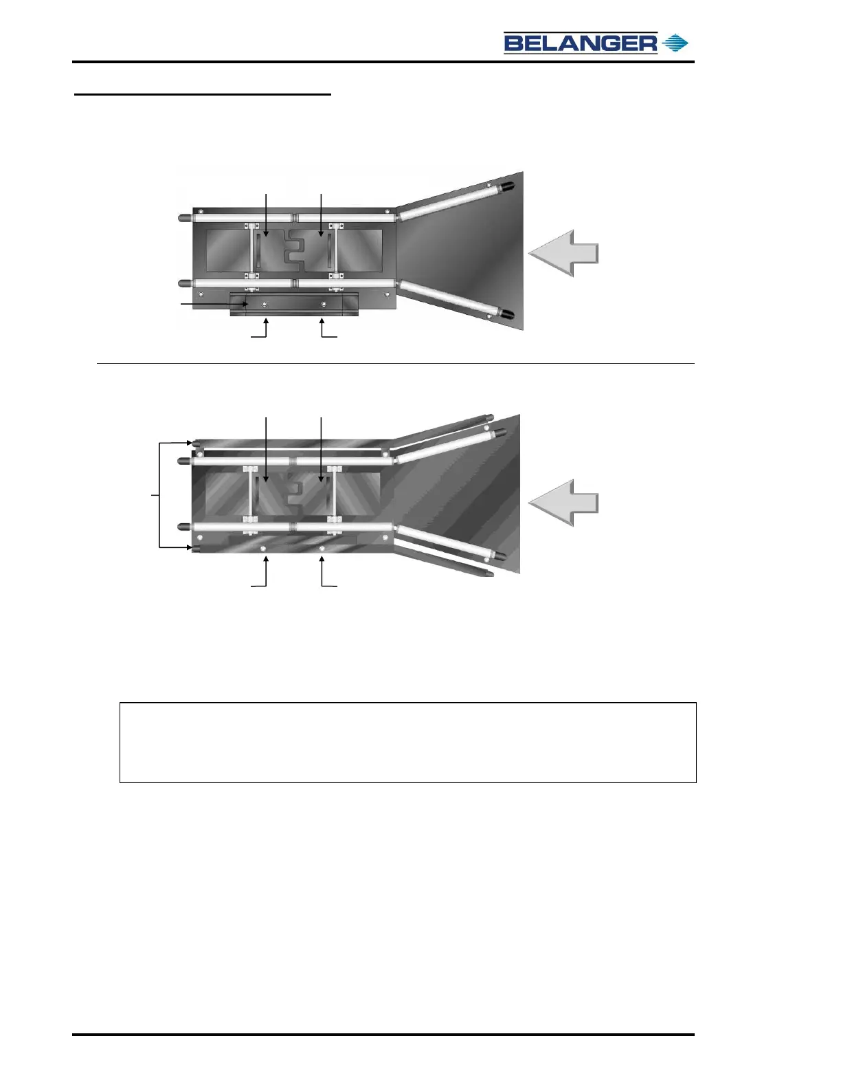
Parts Identification (Standard)
Parts Identification (Dually Option)
4) Using a plumb line, mark the floor across the bay in line with entrance edge of the exit 4” x 6” leg. See the image on the
next page.
5) Snap a line across the bay.
6) Using the centerline of the FreeStyler®, place the components and mark the floor at their locations. See the image on the
next page.
Note: Be sure the Proximity Switches are tightened with pliers (1/4 turn). Failure to do so may
cause switches to fail due to moisture.
Note: If you have the Dually option and you received a Cover Plate, be sure to discard it as it is
used only with the standard style Treadle.