INSTALLATION AND STARTUP
14-6 Belanger, Inc. ®* PO BOX 5470. * Northville, MI 48167-5470 * Ph (248) 349-7010 * Fax (248) 380-9681 1MANUL220
Chapter 14 HydroBlade® Assembly Option
Side Manifold Installation
High Pressure Hoses – Installation
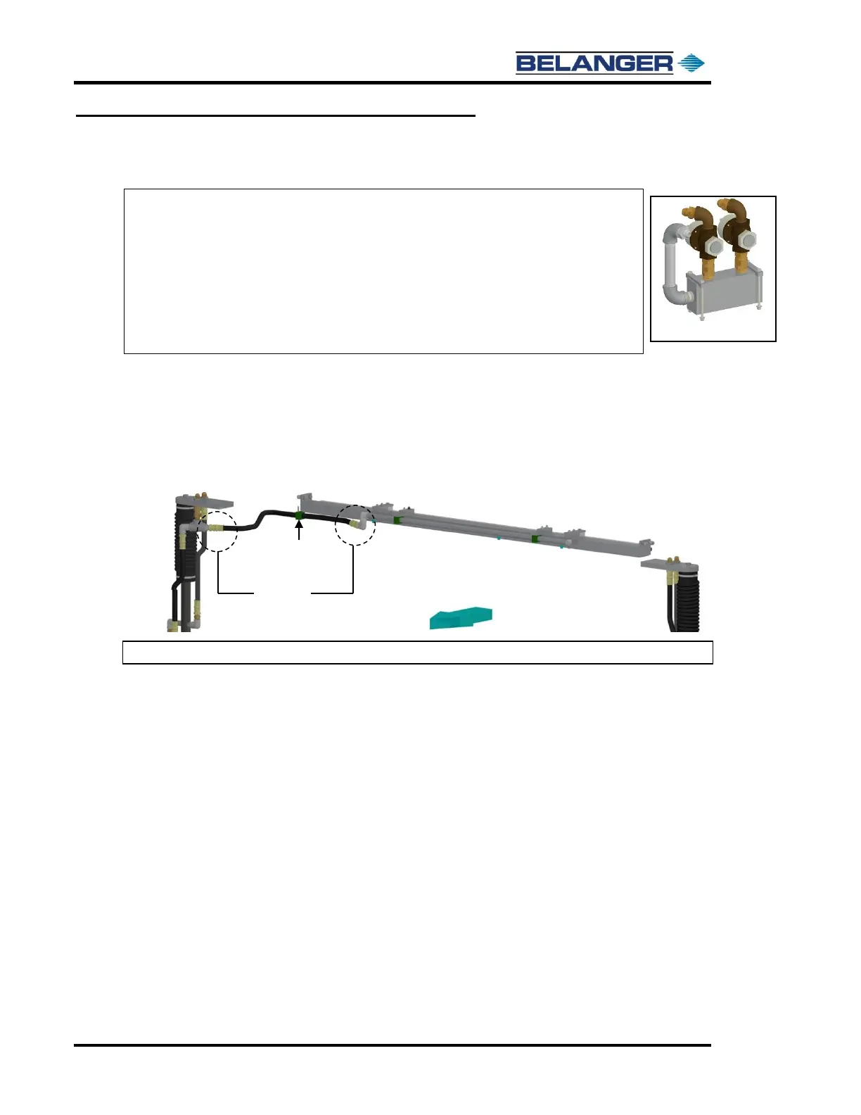
2) Attach the 35’’ hydraulic hose from the Tee on the passenger side bulkhead to the Upper High Pressure
HydroBlade® Spray Manifold attached on the exit side of the cross brace. See the image below.
Completely tighten the 35” hydraulic hose down.
Attach the Stauff™ clamp onto the bottom of the passenger side pod into the two holes that are drilled
on the angle.
Note: At this point all the hose runs on the machine are complete.
See Nozzle Chart later in this chapter for more details.
Note: The Lexair™ Manifold is located inside of the upper utility cabinet on a
channel which is used to mount all the water valves and manifold blocks.
Note: The Lexair™ Manifold is mounted on the side of the machine that is opposite
the boom. For example, if the Boom is mounted to the driver side wall, then this
manifold must be mounted onto the passenger side of the machine.
Note: Standard Boom Mounting and Boom Line Routing is based on the driver side.
If you need a Passenger Side Boom, see “Installing the Boom” in Chapter 4 of
this manual.