INSTALLATION AND STARTUP
1MANUL220 Belanger, Inc.® * PO BOX 5470 * Northville, MI 48167-5470 * Ph (248) 349-7010 * Fax (248) 380-9681 22-9
Chapter 22 Initial Startup
Check Inputs and Motion
Note: At this time, ensure that Input verification is completed correctly. Then verify rail spacing and
boom placement and perform any necessary adjustments. Refer to Chapter 4 for the necessary
procedures to adjust rail spacing or boom placement.
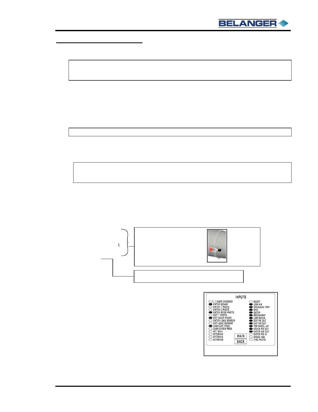
• Set Sonar distance in the HMI (E-1063 Human Machine Interface)
Jog the Carriage 4’-0” from the Entrance End Positive Stop, towards the exit.
Verify that the Sonar is parallel to the floor and not over any drains or obstructions.
If it is over a drain, move the Sonar to the opposite side of the carriage.
Measure the distance from the Sonar face to the floor and record this value in the “FLOOR DISTANCE” field
of the SETUP/MISC screen of the HMI (E-1063 Human Machine Interface).
Note: The height value is what the Sonar currently reads.
Change the SONAR OFFSET to compensate height to equal actual floor distance.
Example: Floor Distance = 119; Height = 115, make SONAR OFFSET 4.
At this point the height should equal floor distance (height will fluctuate, use the most common reading).
Note: For more information on the Multifunctional Sonar Unit see “Sonar Setup” in your HMI
(E-1063 Human Machine Interface) Operation Manual under Sonar Screen Setup and
Sonar Mode Change.
• Verify the following inputs on the HMI (E-1063 Human Machine Interface).
➢ Low Air: Oval filled
➢ Overload Trip: Oval filled
➢ GFCI: Oval filled
➢ E-Stop: Oval filled
➢ Low Water (if option installed): Oval filled
➢ Exit Passenger Side Out
➢ Exit Driver Side Out
➢ Enter Passenger Side Out.
➢ Enter Driver Side Out
➢ Top Wheel Up
➢ Enter Passenger Side In:
Move the entrance passenger side arm in toward the vehicle (all the
way) and verify that the oval is filled.
Adjust the Reed Switch if necessary.
➢ Bit 1, 2, 3 and 4 from POS: Oval should be clear on all 4 and filled when
any of them has a Package selected at the POS.
➢ Home the machine from the HMI (E-1063 Human Machine Interface) at
the USER/CARRIAGE HOME (see Input Screen at right)
➢ Press CARRIAGE FIND LIMIT from the User Screen. The carriage will
slowly move from the exit to the entrance to measure the rail length.