INSTALLATION AND STARTUP
3-12 Belanger, Inc.® * PO BOX 5470. * Northville, MI 48167-5470 * Ph (248) 349-7010 * Fax (248) 380-9681 1MANUL220
Chapter 3 Getting Started
Installation Overview
Length Considerations
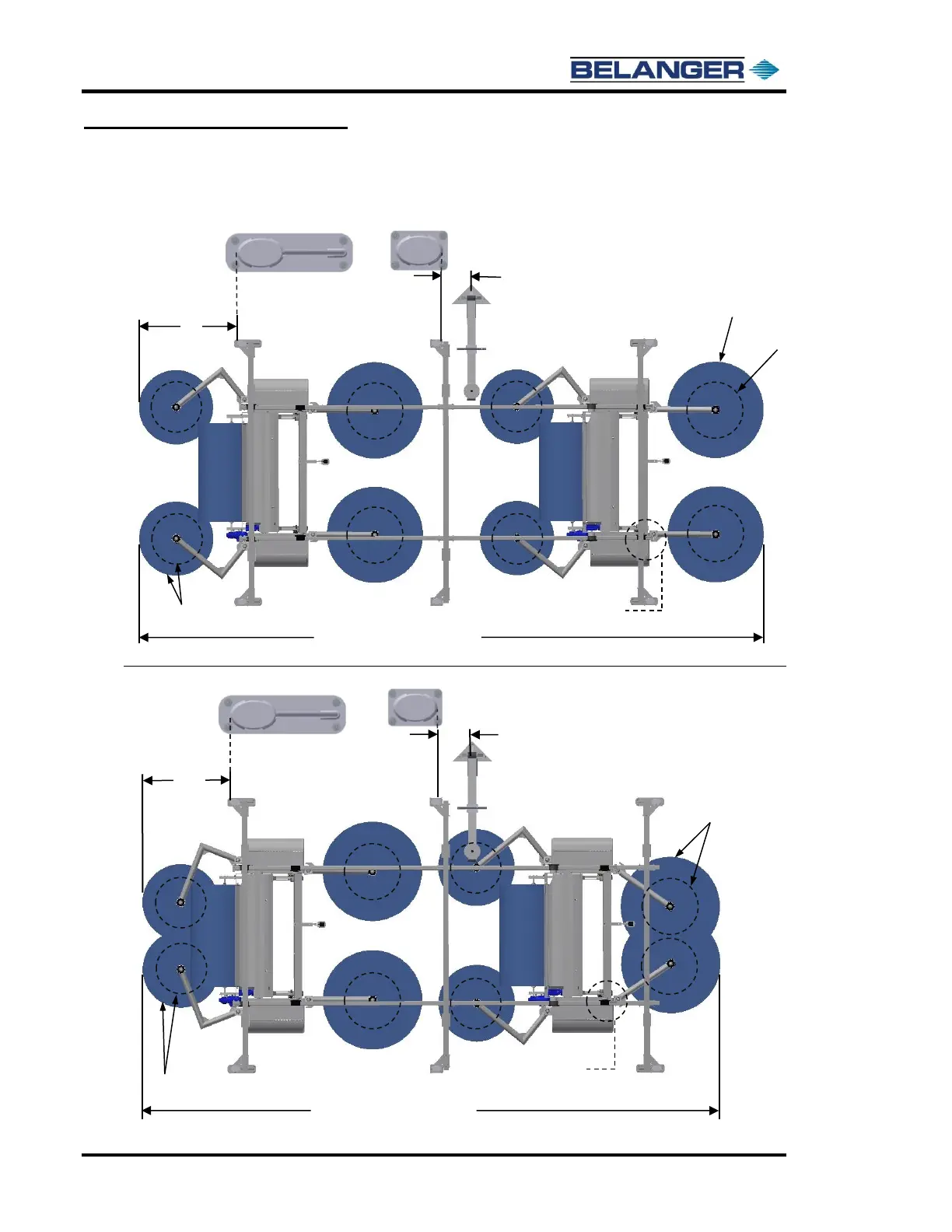
Oval 6-Legged Frame: Configuration #2 Standard Bay Length (37’-0” bay)
Oval 6-Legged Frame: Configuration #2 Small Bay Length (34’-6” bay)
21’ – 9” Vehicle Conditions:
Small Bay Software (37’-0”)
Position of Positive Stop
Clamps will be determined
by the bay length
The 66” dimension is taken
from the exit edge of the leg
The 22-1/8” dimension is
taken from center of Boom
Mount to the entrance edge
of the center leg
Machine
Entrance
Position
21’ – 9” Vehicle Conditions:
Small Bay Software (34’-6”)
Wheels begin spinning in this position
Machine
Entrance
Position
The 52” dimension is taken
from the exit edge of the leg
The 22-1/8” dimension is
taken from the same location
as the above image
Positive Stop Clamps
Moved In 30”
45” Diameter
when Spinning
70” Diameter
when Spinning
54” & 39” Diameter
when Spinning
See top image for diameter of
wheels when spinning
See top image for diameter of
wheels when spinning