INSTALLATION AND STARTUP
4-20 Belanger, Inc.® * PO BOX 5470. * Northville, MI 48167-5470 * Ph (248) 349-7010 * Fax (248) 380-9681 1MANUL220
Chapter 4 Frame and Carriage Assembly
Installing the Boom Mount
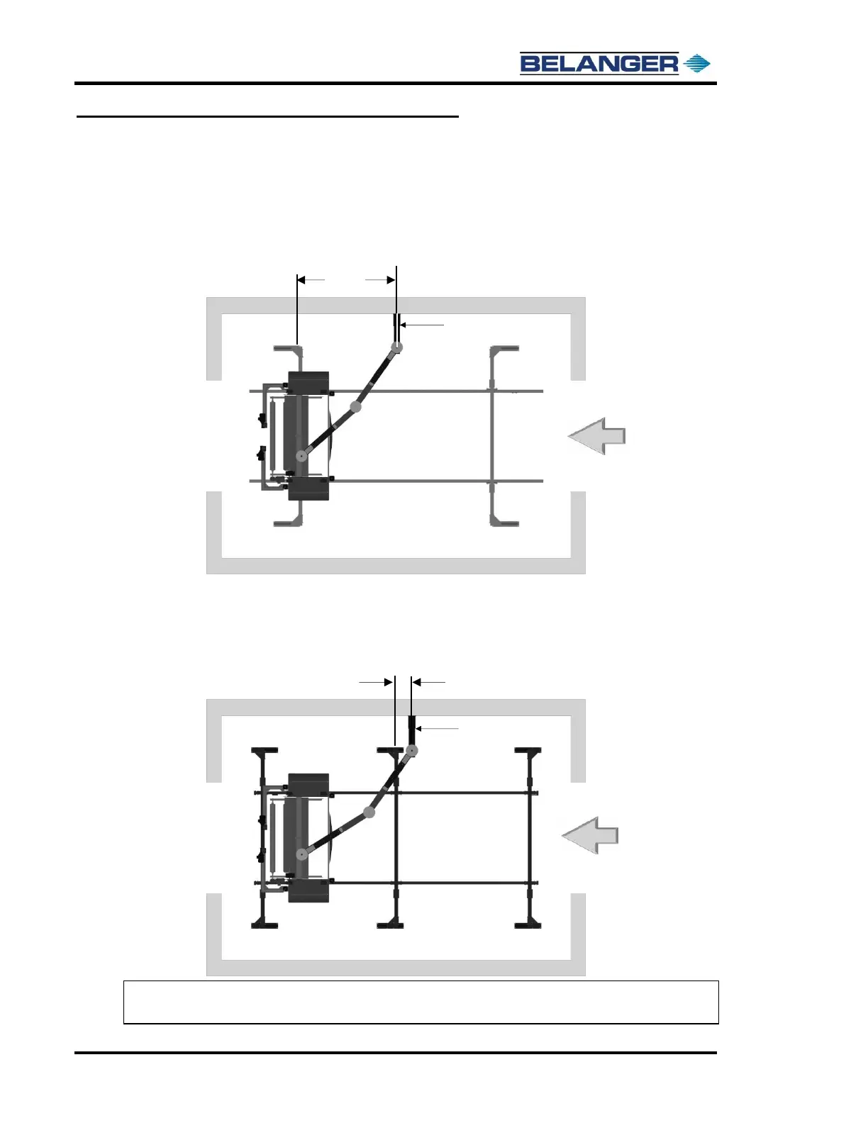
3) The images below show the location to mark the wall for bay depth placement of the Wall
Mount.
For the bay depth location with a 4-Legged Frame measure 124-1/2” from the entrance
side edge of the exit leg toward the entrance of the bay and mark the wall for this
dimension. This mark will be used to line up the center of the Wall Mount in Step 4.
For the bay depth location with a 6-Legged Frame measure 22-1/8” from the entrance side
edge of the center leg toward the entrance of the bay and mark the wall for this dimension.
This mark will be used to line up the center of the Wall Mount in Step 4.
Note: All the above dimensions are applicable for either Driver side or Passenger
side Boom orientation.