INSTALLATION AND STARTUP
1MANUL220 Belanger, Inc.® * PO BOX 5470. * Northville, MI 48167-5470 * Ph (248) 349-7010 * Fax (248) 380-9681 4-23
Chapter 4 Frame and Carriage Assembly
Installing the Optional Freestanding Boom Mount Leg
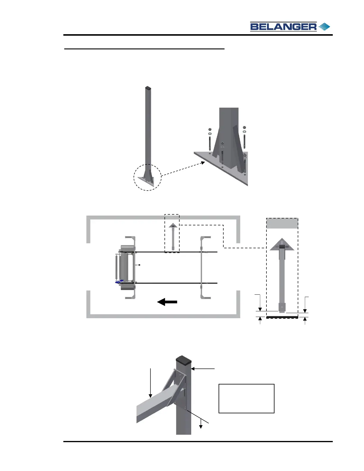
2) Once the position of the Freestanding Boom Mount Leg has been determined secure the leg
to the floor using the supplied 5/8” lag bolts (1FSTNR-ST750), as shown below.
3) Determine the Boom Mount length by measuring the distance from the inside surface of the
Freestanding Boom Mount Leg to the outside surface of the rail and subtract 3-1/2” as shown
below. Cut the Boom Mount to the determined length.
4) Then on the Freestanding Mount Leg measure up 112-7/8” from the floor and mark the bay
height dimension for the Boom Mount Assembly. This mark will be used to line up the bottom
edge of the detail plate on the Boom Mount Assembly.