INSTALLATION AND STARTUP
1MANUL220 Belanger, Inc.® * PO BOX 5470. * Northville, MI 48167-5470 * Ph (248) 349-7010 * Fax (248) 380-9681 4-27
Chapter 4 Frame and Carriage Assembly
Passenger Side Boom Install
Optional HydroBlade®/ Wheel Cleaner Manifold Accessories
To reorient the components shown below from a Driver side equipment room to a Passenger side
equipment room configuration; see the following instructions:
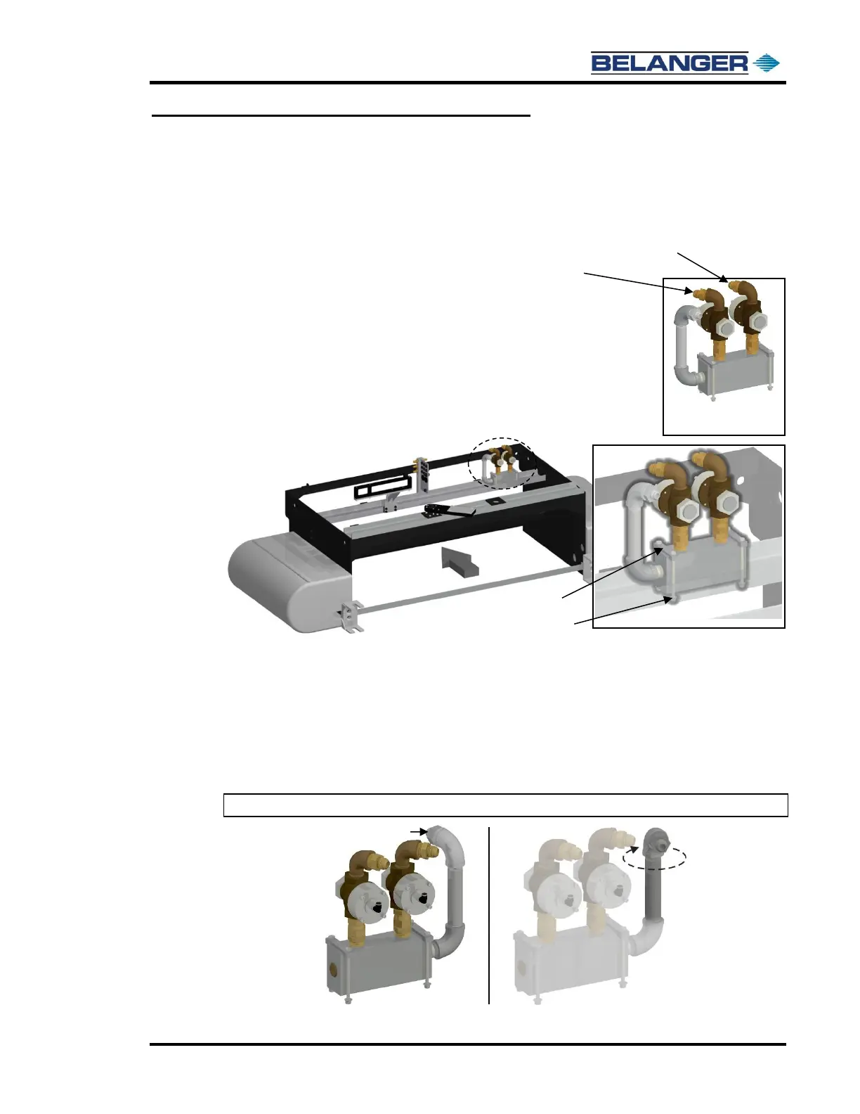
Lexair™ Distribution Manifold
1) Locate the Lexair™ Manifold assembly near the top of the carriage on the passenger
side.
Disconnect both ends of each hydraulic hose (2) that is routed from the
Lexair™ Manifold to the Center Feed Manifolds. See the image to the right.
2) Remove the four 5/16-18 fasteners, flat washers, Nylock™ nuts, and the two clamps
that are holding the manifold assembly to the carriage c-channel as shown below.
3) Move the manifold assembly to a workbench that has a vice on it so that you can rotate the fittings around to
their appropriate orientation.
Once at the workbench, loosen the brass swivel fittings that hold the Lexair™ Valves in place.
Remove the Lexair™ Valves and set them off to the side.
4) Turn the top elbow so that the Main Feed Connection faces the entrance side of the machine and is angled
toward the outside of the carriage as shown below.
Note: Make sure that all the other fittings stay tight!