INSTALLATION AND STARTUP
4-34 Belanger, Inc.® * PO BOX 5470. * Northville, MI 48167-5470 * Ph (248) 349-7010 * Fax (248) 380-9681 1MANUL220
Chapter 4 Frame and Carriage Assembly
Routing Boom Utilities
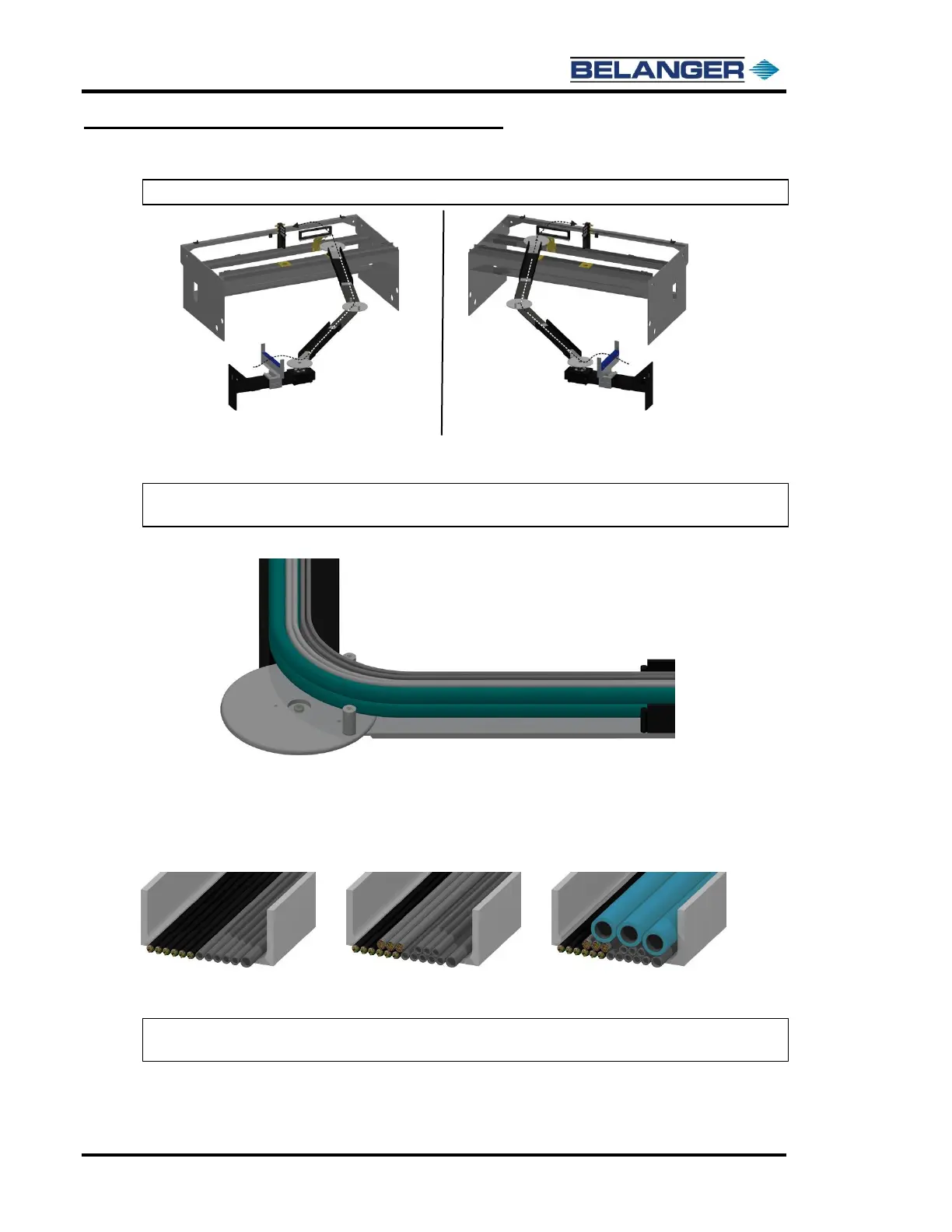
Note: The images below show the route necessary to lay out the utilities.
3) Locate your field supplied poly-flow tubing and hoses.
Run the hoses over the white plastic disk through the wall or freestanding mount boom arm,
through the machine mount boom arm, and onto the machine.
Note: Make sure the tubing and hoses have an acceptable bend radius, as shown below. The
smallest bend radius for the lines on the machine is at the entrance end.
4) First, lay the 6 motor leads, 5 field supplied 3/8” poly flow tubes, and the single 1/2” main air poly
flow tube into the bottom of the channel.
Lay the 3 umbilical cords on top of the previously laid items.
Lay the 3 water hoses on top of the Umbilical cords
Place each group of lines on the outside of the bend radius, as shown in step 3.
Note: When all utility hoses and tubes are in place, there should be sufficient slack to avoid any
binding of the hoses.
6 motor leads, the 5 field supplied
3/8” poly-flow tubes and the single
1/2” main air poly-flow tube