INSTALLATION AND STARTUP
4-38 Belanger, Inc.® * PO BOX 5470. * Northville, MI 48167-5470 * Ph (248) 349-7010 * Fax (248) 380-9681 1MANUL220
Chapter 4 Frame and Carriage Assembly
Optional Deluxe Boom
Connecting the Boom
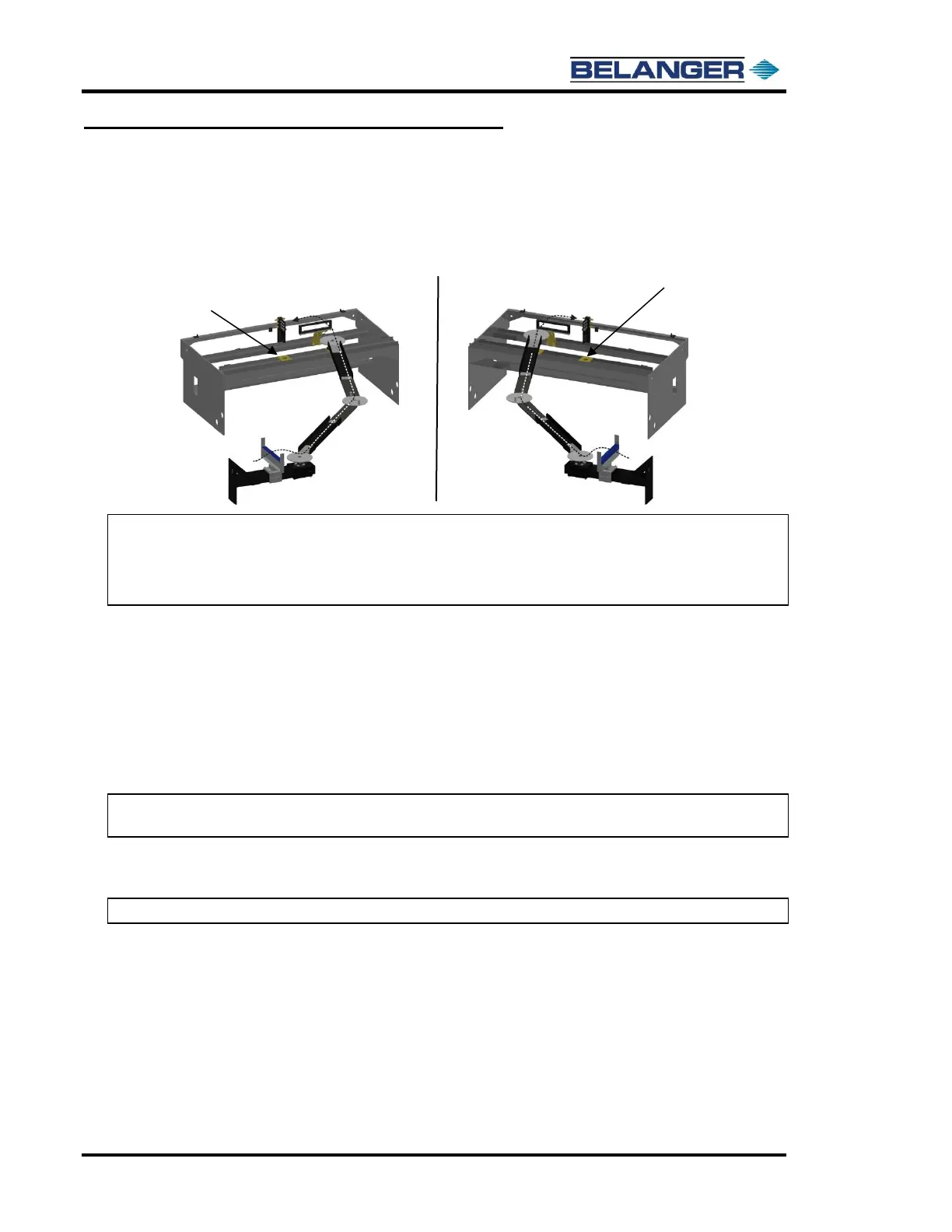
• The orientation of the boom arms depends on whether the boom is on the driver side or passenger side of the wash.
Mount each arm in its proper location. The images below show how the Boom Assembly will be rotated to
accommodate the equipment room on either side.
Note: If the Boom Wall or Freestanding Mount Leg is on the Passenger side, the Boom Arm will
connect to the Carriage Assembly on the Driver side.
Note: If the Boom Wall or Freestanding Mount Leg is on the Driver side, the Boom Arm will connect
to the Carriage Assembly on the Passenger side
• The next step requires 6 lengths of liquid tight plastic tubing to be routed at each end of the boom and at the center
of the boom.
Run two 50-inch lengths of liquid tight tubing on the wall side of the boom.
Run a 28-inch length of liquid tight tubing in the center of the boom on the inside.
Run a 33-1/2” length of liquid tight tubing in the center of the boom on the outside.
Run the remaining 2 lengths of 28” of liquid tight tubing on the machine side location.
Note: It will be simpler to run the utility lines if the plastic tubing is not attached until after the utility
lines are routed through the tubing.
• Due to factory pre-set wiring, it is important to route the electrical wires through the appropriate boom tubes. Care
is also needed to ensure that air lines are run from pump locations through the appropriate boom tubes
Note: Use the procedure that begins on the next page to route utilities properly through the boom.