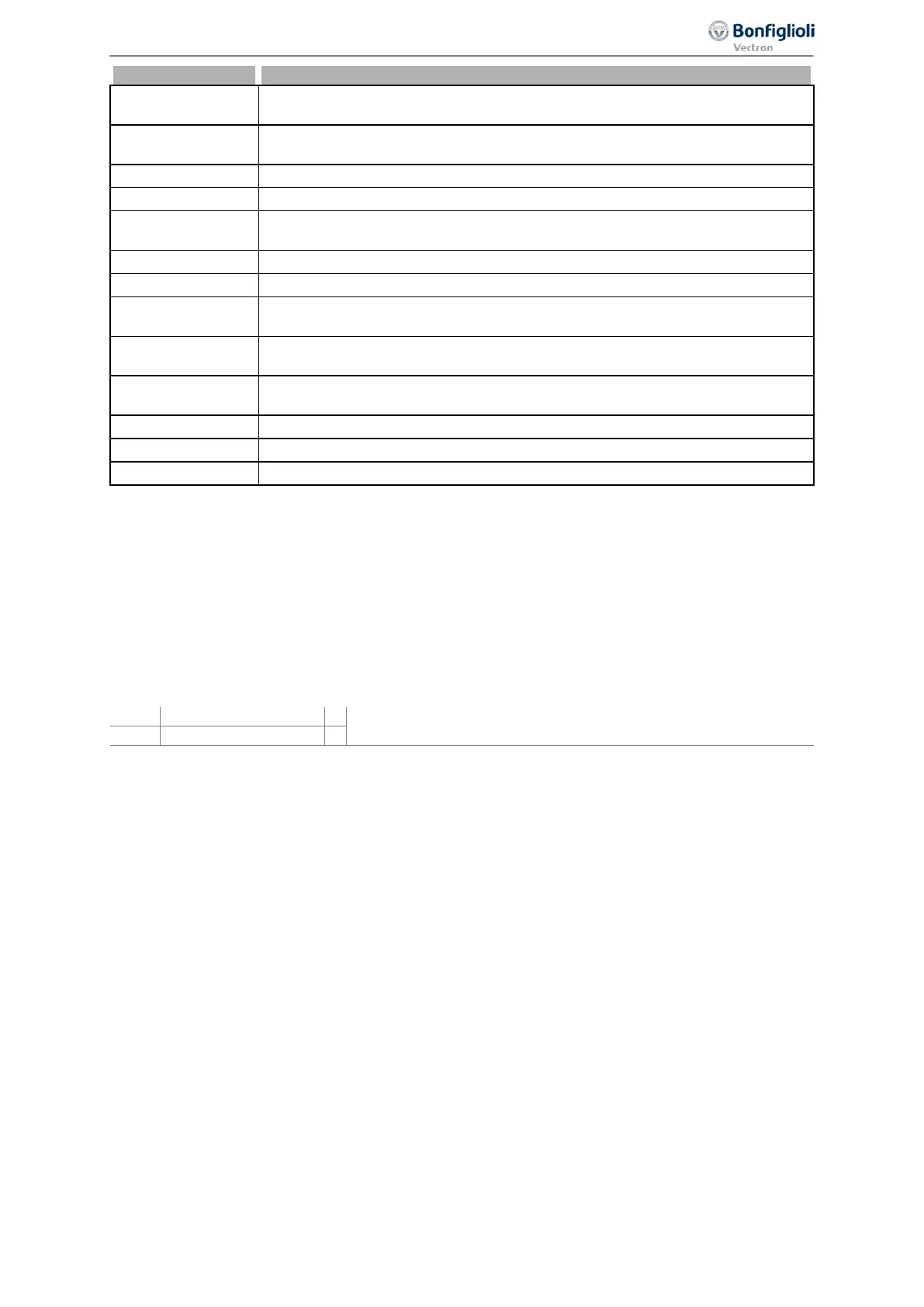
Operational and error diagnosis
A 00 08 Tc
Maximum heat sink temperature T
K
minus the Warning Limit Heat Sink Temp.
407 reached.
A 00 10 Ti
Maximum inside temperature T
i
minus the Warning Limit Inside Temp. 408
reached.
A 00 20 Lim
The controller stated in
limits the reference value.
A 00 40 INIT Frequency inverter is being initialized
A 00 80 PTC
Warning behavior according to parameterized Operation Mode Motor Temp.
570 at maximum motor temperature T
Motor
.
A 01 00 Mains
576 reports a phase failure.
A 02 00 PMS
Motor circuit breaker parameterized in
571 tripped.
A 04 00 Flim
The Maximum Frequency 419 was exceeded. The frequency limitation is ac-
tive.
A 08 00 A1
The input signal MFI1A is lower than 1 V / 2 mA according to the operation
mode for the Error/Warning Behaviour 453.
A 10 00 A2
The input signal MFI2A is lower than 1 V / 2 mA according to the operation
mode for the Error/Warning Behaviour 563.
A slave on the system bus signals an error.
The DC link voltage has reached the type-dependent minimum value.
A 80 00 WARN2
In
Application Warning State
367, a warning is present.
Example:
The following warning status is displayed:
A008D Ixt IxtLt Tc PTC
The warning status results from the hexadecimal sum of the warning codes (0001+0004+0008+0080
= 008D).
The short-term overload (1 s), warning limit heat sink temperature and warning limit motor tempera-
ture warnings are present.
Warnings are signaled via digital signals.
Signal if a message is output via Warnings 269.
1)
For linking to frequency inverter functions
2)
For output via a digital output. Select the signal source for one of the parameters 531, 532, 533,
554. See chapter
7.6.5 "Digital outputs".
337
Warning status and warning status application 06/2013 Operating Instructions
Agile

 Loading...


