68/188 Installation
Bosch Rexroth AG, MIT: ActiveMover, 3 842 564 874/2021-04
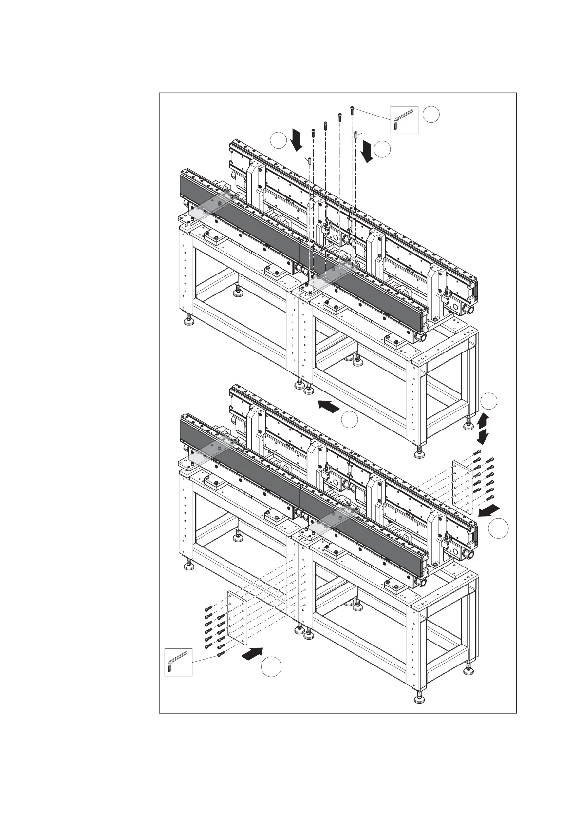
Fig. 44:
9
6
(4x)
7
SW8
8x
16x40
88
8
SW8
12x
557 186-43
12x40
10
10
A
B
A
B
M
D
=80 Nm
M
D
=80 Nm
Connecting system sections, using the example of 2 section modules (1)
6. Position the system
section (B) to be
connected below the
connection plate of
the reference system
section (A).
7. Align the system section
longitudinally, crosswise
and at the same height
as the fi rst system
section (see fi g. 42
on page 66).
8. Add 2 straight pins
for fi xing to the upper
connection plate.
9. Screw on the upper
connection plate loosely.
10. Mount the side
connection plates
(on both sides).