2 • Description
Doc. 065051-03 1/08 43
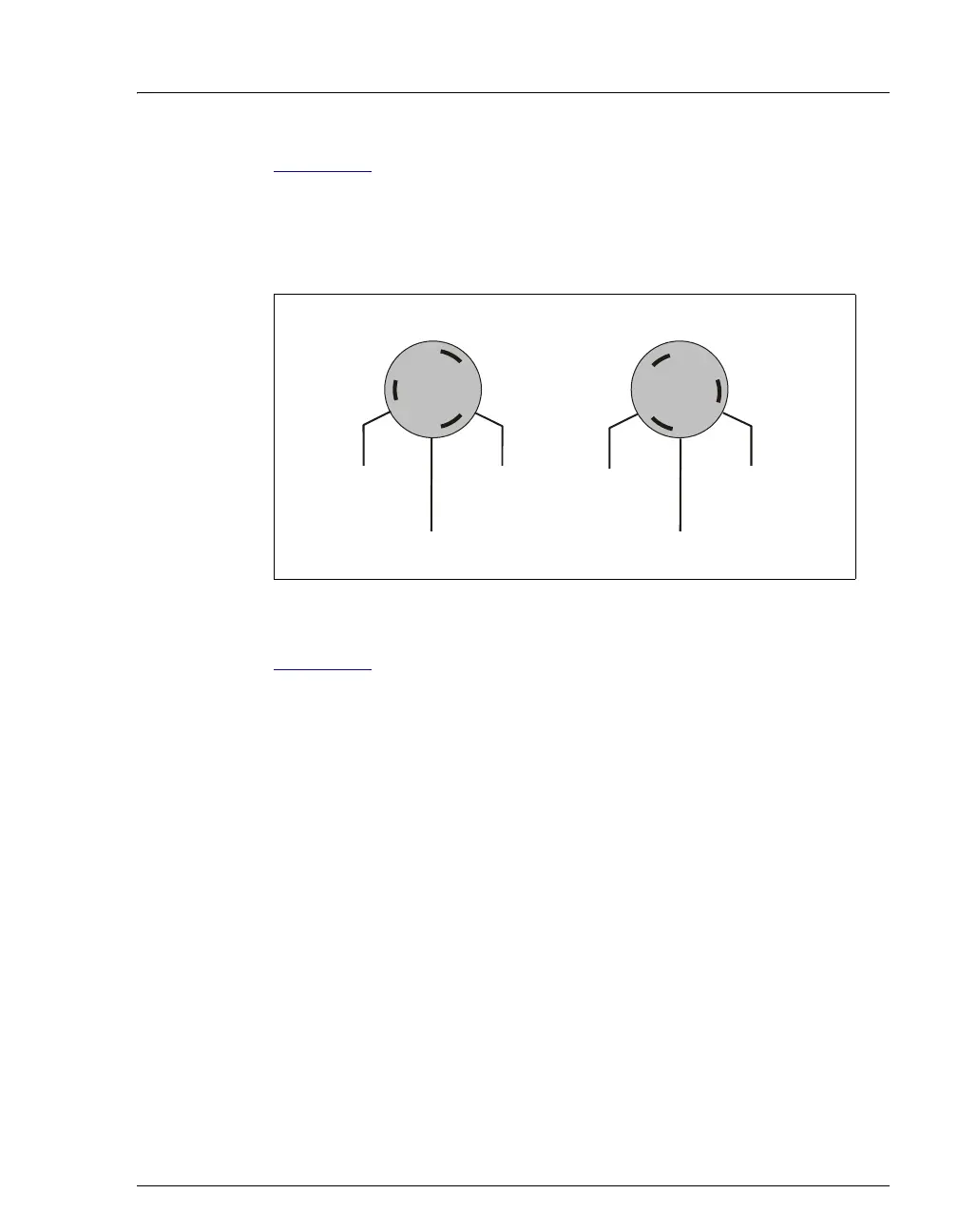
Figure 2-23 shows the flow paths through the sample syringe valve ports
for the two valve positions:
• In the needle position, flow is between ports A–B, C–D, and E–F.
• In the flush position, flow is between ports A–F, B–C, and D–E.
Figure 2-24
shows the fluid connections to the sample syringe, flush
reservoir, sample prep syringe, and reagent reservoirs when the sample
prep option is installed.
Figure 2-23. Sample Syringe Valve Port Flow Path Schematics
ee
e
os
t
on
To Flush
Reservoir
To Sample
S
rin
e
To Sampling
Needle
us
os
t
on
To Flush
Reservoir
To Sample
S
rin
e
To Sampling
Needle
A
B
C
D
E
F
B
C
D
E
F