F6000 Family of Power System Simulators User Guide
72A-1589 Rev. C 02/01 4-3
D
DD
D
R
RR
R
A
AA
A
F
FF
F
T
TT
T
3
33
3
/
//
/
5
55
5
/
//
/0
00
0
1
11
1
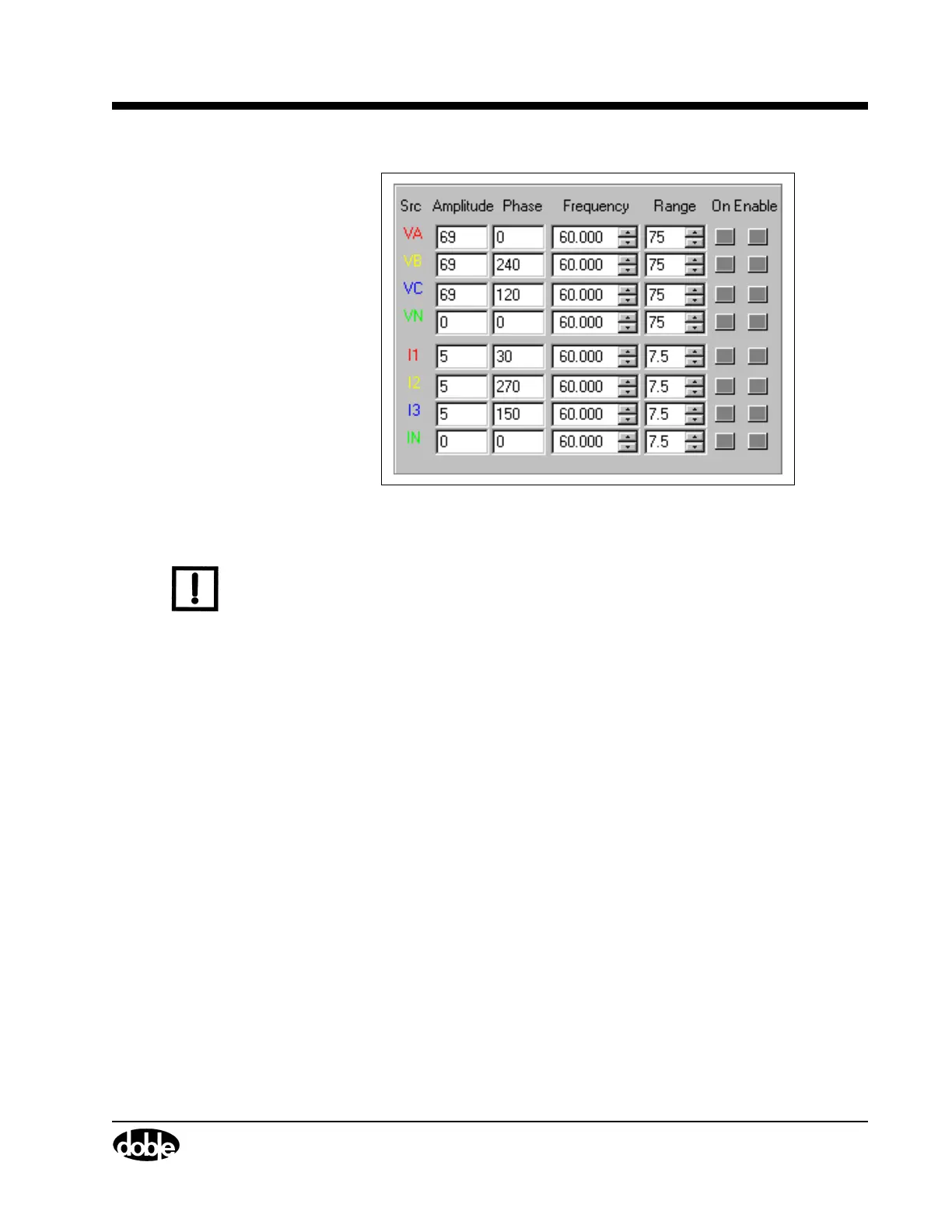
Figure 4.2 Source Table
N
OTE
If a source error occurs, the alarm is visible in the source table. The
name of the source affected changes to ER and blinks. The Amplitude
and Phase fields for that source also blink, and an audible alarm sounds
from the speakers of the control PC. See ”Source Errors” on page 6-14.
The first five columns contain the settings for each source:
Source The source column in Figure 4.2 contains eight
entries for eight sources. The standard naming
scheme for the voltage sources is VA, VB, VC, and
VN; the standard naming scheme for the current
sources is I1, I2, I3, and IN.
Amplitude Amplitude indicates the voltage or current value of
a source. The range sets the maximum value for
the amplitude. If the amplitude entered exceeds the
maximum range value, an error message appears.
To correct the error, reduce the amplitude or
increase the range.
Phase The phase indicates the phase angle in degrees.
Enter a phase angle from –359.9° to 0° to +359.9°.