EasyManua.ls Logo

FICEP 32292 - Page 44

Default Icon
226 pages
Print Icon
To Next Page IconTo Next Page
To Previous Page IconTo Previous Page
Loading...
Programming and operating manual Model 1001 DFB
44 FICEP S.p.A.
Fields description:
Reference
Meaning
F1÷ F6 rows
L.H. side
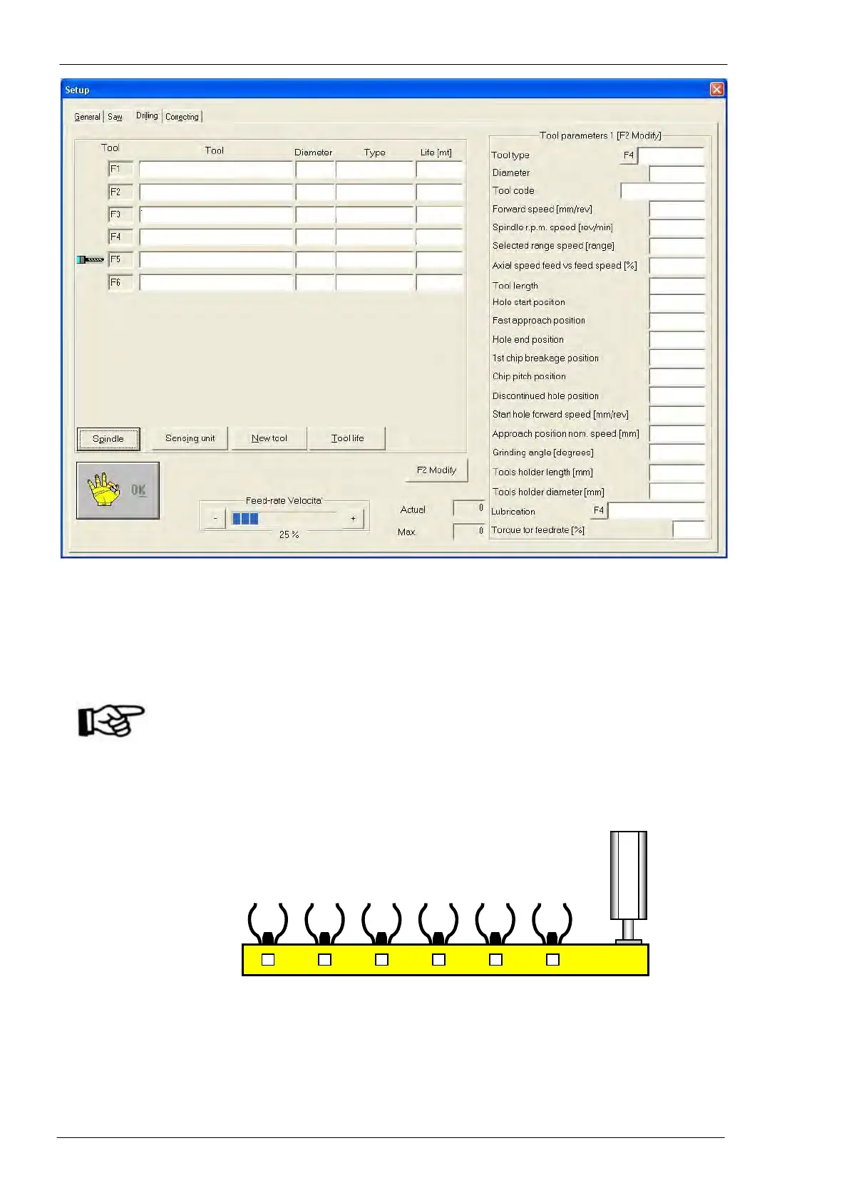
Each line corresponds to the tool placed in the relative forked site of tools magazine (F1
= site 1, F2 = site 2, etc…); the row with a tool icon corresponds to the tool inserted into
the spindle.
ATTENTION: If a tool is inserted into the spindle, its place in the magazine must be
empty and the related row in the setup window must have the tool icon. If
the icon is not present, the operator can press the push-button “Spindle”
and type in the number of the empty site. Typing in “0it signified that no
tool is inserted into the spindle and each tool is in its own place in the
tools magazine; in this case, the icon disappears.
01
Tool code (see “Tables” field 01)
02
Tool nominal diameter (see “Tables” field 02)
03
Additional identification code defined by the user (see “Tables” field 06)
04
Spindle forward speed entering the material (see “Tables” field 09)
05
Spindle rotation speed (see “Tables” field 08)
06
Range number of spindle rotation speed (only for geared spindle)
1
2
3
4
5
6
01
02
03
04
05
06
07
08
09
10
11
12
13
14
15
16
17
18
19
20
21
22
23
24

Table of Contents

Related product manuals