259
────────────────────────────────────────────────────
14.2 Type and Amount of Data That Can Be Saved
────────────────────────────────────────────────────
1
2
3
4
5
6
7
8
9
0
1
2
3
4
A
1.FD output date and time
2.Instantaneous values
Instantaneous value dat
at the time of output to th
floppy disk
Voltage(U1, U2, U3, Uave
Current(I1, I2, I3, Iave)
Power(P, Q, S, λ, f)
3. Maximum values
Voltage(U1, U2, U3)
Current(I1, I2, I3)
Power(P, Q, S, λ, f)
4.Minimum values
Voltage(U1, U2, U3)
Current(I1, I2, I3)
Power(P, Q, S, λ, f)
1.FD output date and time
2.Integration start time,
integration elapsed time
4.2 Type and Amount of Data That Can Be Saved
The settings for the data items that are to be saved are the same as for the
items that are output to the printer; these print/save items for each
measurement mode are used to determine what data is saved to floppy disk.
For details on the specific setting method, refer to the respective section
entitled "Print/Save Items" in the chapter for each measurement mode.
Note that these items apply to both automatic output and manual saves.
In addition, the items that can be saved differs, depending on whether the
reactive power meter method is used or not.
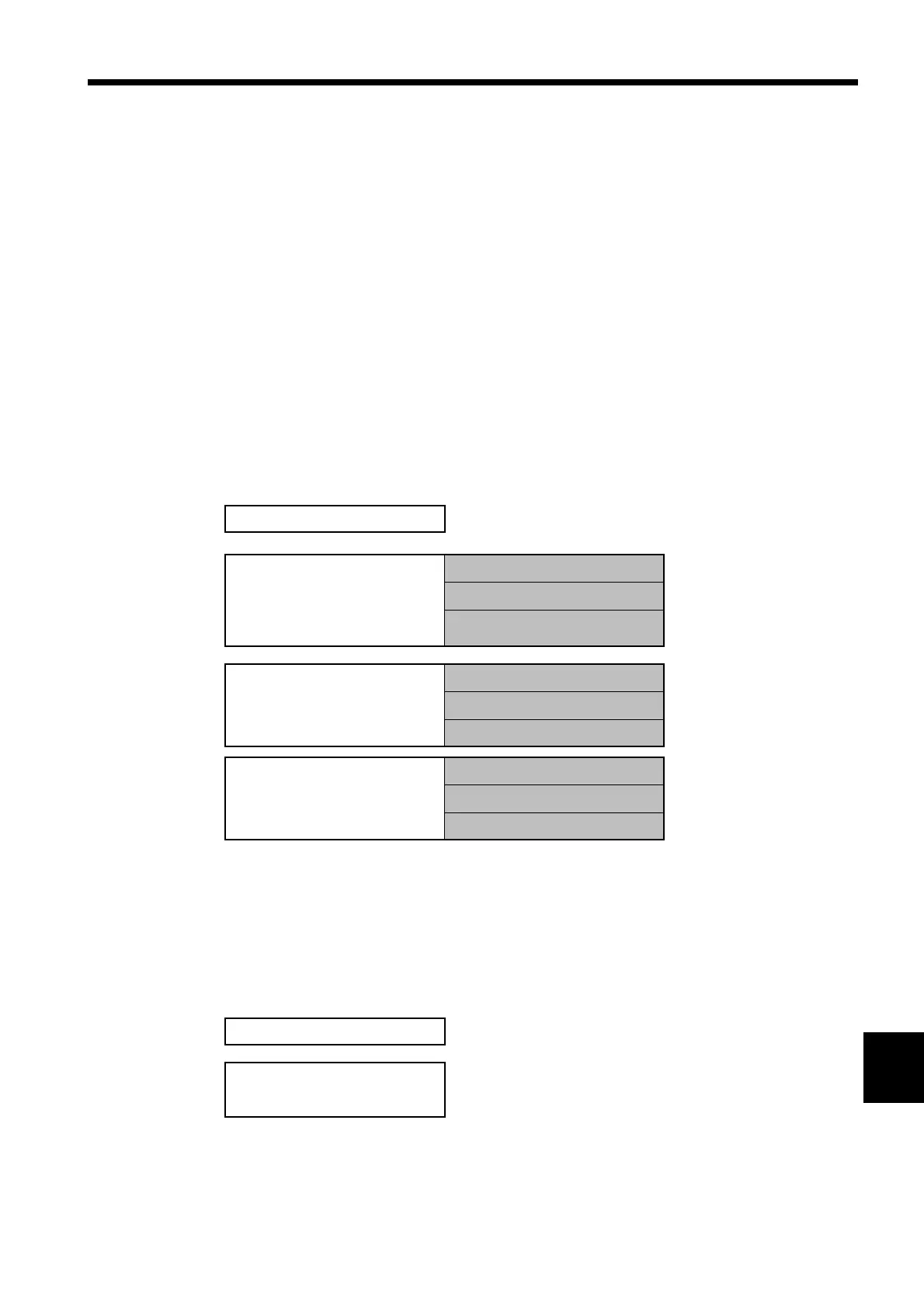
(1) Data that can be saved
●Normal Measurement mode
* The minimum/maximum data includes the time at which the minimum or
maximum was generated.
* Items 3 and 4 represent data that was tabulated from the time that the data
reset key was pressed until the FD output time.
●Integrated Measurement mode