5.3 Application Settings
178
• Selecting or as the contact check timing causes the trigger synchro-
nous output function to be automatically turned on.
See: "5.3.1 Applying the Signal to the Sample Only during Measurement (Trigger Synchronous
Output Function)" (p. 171)
• When setting a contact check threshold, a wait time may occur depending on the timing.
(p. 352)
• When the memory function has been enabled
• When the contact check timing has been set to
• When a contact check error has been displayed (p. 360)
• No contact judgment can be made in the following circumstances:
• When the instrument's memory becomes full partway through a series of frequency
points ( will be displayed) (p. 179).
• When the measurement mode is changed partway through a series of frequency points
• When the sample is a high-capacitance capacitor, the contact check function may not
operate under some measurement conditions.
• If an error occurs during contact check operation, an error will be displayed at the top left
of the screen, as shown in the following figure.
Set the contact check threshold with and
.
4
Settable range : 1 to 5
Contact Check Settings
Threshold 1 2 3 4 5
Permissible
contact
resistance []
Approx.
1000
Approx.
500
Approx.
100
Approx.
50
Approx.
10
5
Press to close the setting screen.
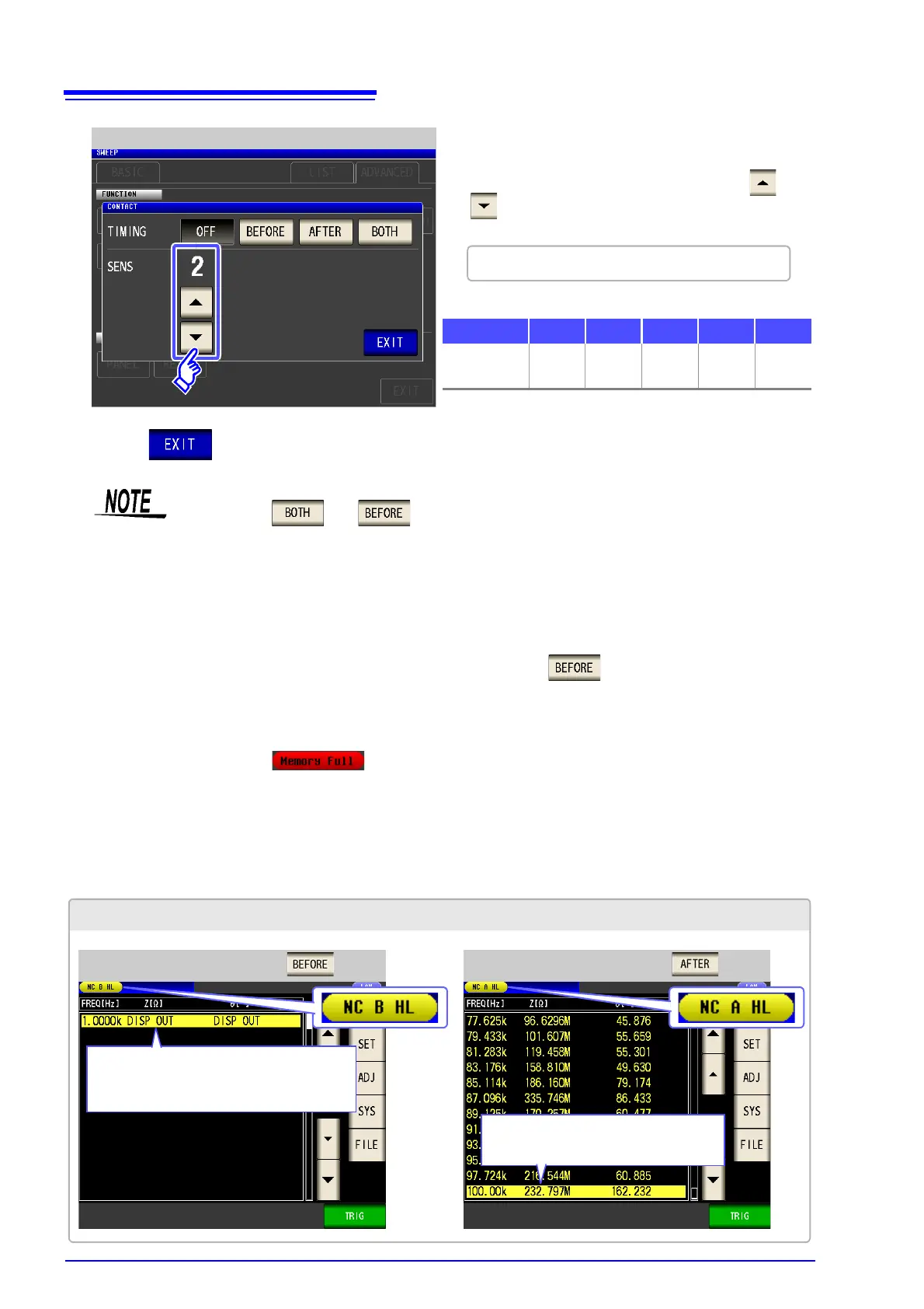
Example display when an error occurs during contact check operation
DISP OUT will be displayed for the initial
sweep point, and subsequent measure-
ments will not be performed.
Any error will be detected at the last
sweep point.
When the timing is set to When the timing is set to