4.2 Setting Basic Settings of Measurement Conditions
55
4
Chapter 4 LCR Function
The constant current operation range differs depending on the test sample to be measured.
The impedance Zm' observed from the generator is as follows:
Accordingly, the voltage
Vm across both leads of the sample is as follows:
Because the generator output voltage range is 5[mV] to 5[V], the CV operation range per
the above expression is
Vm = 0.8[mV] to 0.78[V].
In low Z high accuracy mode, the output resistance
Ro becomes 25 [].
Ro: Output resistance (100 [])Zm' = Ro + Zm = 100 [
] - j15.9 [
]
Vm
Zm Vo
Zm
----------------------
15.9
Vo
101.3
--------------------------
==
Vo : generator output
|Zm' |
15.9 [
] × Vo
Constant current (CC) mode setting
Measurement mode (p. 72) Normal mode Low Z high accuracy mode
Constant current setting range 0.01 mA to 50.00 mA 0.01 mA to 100.00 mA
Constant current accuracy ±10%rdg. ±10 A ±10%rdg. ±10 A
Output impedance 100 ±10 25 ±5
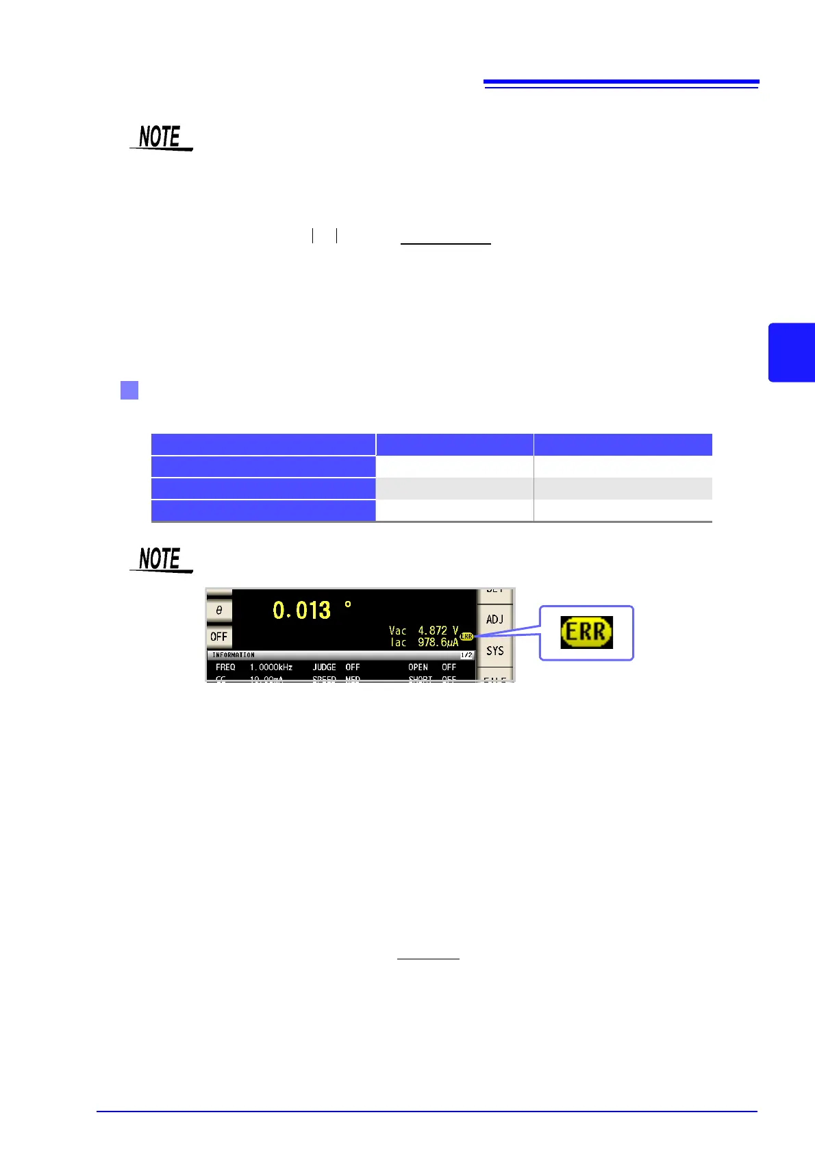
Testing some types of sample is not possible using constant current. In this case, the following
symbol appears on the display:
Constant current measurement will not be performed.
Change the constant current level so that it is less than or equal to the displayed Iac monitor
values.
Example: When a 1 mH impedance is measured at 1 kHz, the CC operation range can be
obtained as follows.
Sample impedance
Zm becomes as follows:
The impedance
Zm' observed from the generator is as follows:
Accordingly, the current
Im across both leads of the sample is as follows:
Because the generator output voltage range is 5 [mV] to 5 [V] (see the table of page 54),
the CC operation range per the above expression is
Im = 49.9[A] to 49.9[mA].
In low Z high accuracy mode, the output resistance
Ro becomes 25 [].
Xm 2
fL=
Zm
= Rm + jXm = 0 [
] - j6.28 [
]
Ro: output resistance (100 [])Zm' = Ro + Zm = 100 [
] - j6.28 [
]
Im
Vo
Zm
------------
Vo
118.1
------------------==
Vo : generator output
|Zm' |
Vo
100.2 [
]