259
a. Select Network > IPv6 Routing from the navigation tree of Switch C.
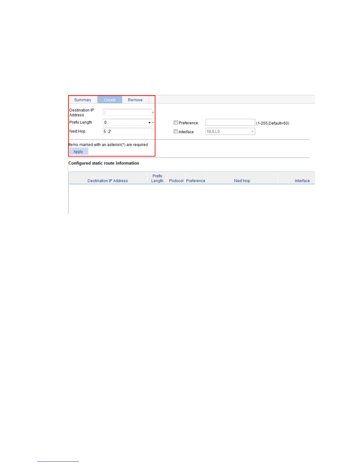
b. Click the Create tab.
c. Enter :: for Destination IP Address, select 0 from the Prefix Length list, and enter 5::2 for Next
Hop.
d. Click Apply.
Figure 243 Configuring a default route
Verifying the configuration
1. Display the routing table:
Enter the IPv6 route page of Switch A, Switch B, and Switch C to verify that the newly configured
static routes are displayed as active routes on the pages.
2. Ping Host C from Switch A:
<SwitchA> system-view
[SwitchA] ping ipv6 3::2
PING 3::2 : 56 data bytes, press CTRL_C to break
Reply from 3::2
bytes=56 Sequence=1 hop limit=254 time = 63 ms
Reply from 3::2
bytes=56 Sequence=2 hop limit=254 time = 62 ms
Reply from 3::2
bytes=56 Sequence=3 hop limit=254 time = 62 ms
Reply from 3::2
bytes=56 Sequence=4 hop limit=254 time = 63 ms
Reply from 3::2
bytes=56 Sequence=5 hop limit=254 time = 63 ms
--- 3::2 ping statistics ---
5 packet(s) transmitted
5 packet(s) received
0.00% packet loss
round-trip min/avg/max = 62/62/63 ms
 Loading...